High propagation speed coaxial and twinaxial cable

a coaxial and twin-coaxial cable technology, applied in the direction of power cables, cables, insulated conductors, etc., can solve the problems of air alone not being able to provide structural stability, and the combination of characteristics being difficult to realize commercially

Inactive Publication Date: 2004-04-22
3M INNOVATIVE PROPERTIES CO
View PDF6 Cites 23 Cited by
  • Summary
  • Abstract
  • Description
  • Claims
  • Application Information

AI Technical Summary

Problems solved by technology

Of course, air alone cannot supply structural stability; and therefore some relatively solid dielectric spacer must be included in an "air core" cable.
This combination of characteristics has proven difficult to realize commercially, as the following prior art illustrates.
The circular monofilaments have the drawback of placing circular cross-sectioned solid dielectric in close proximity to the inner conductor and thus increa...

Method used


Image

  • High propagation speed coaxial and twinaxial cable
  • High propagation speed coaxial and twinaxial cable
  • High propagation speed coaxial and twinaxial cable

Examples


first embodiment

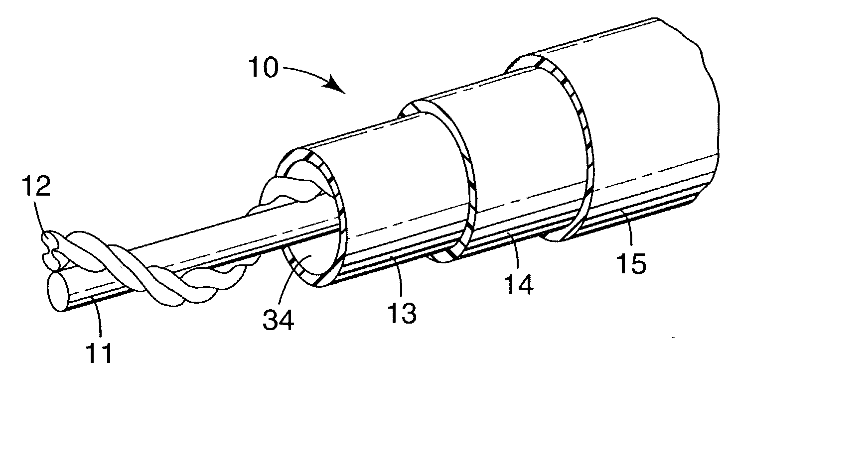
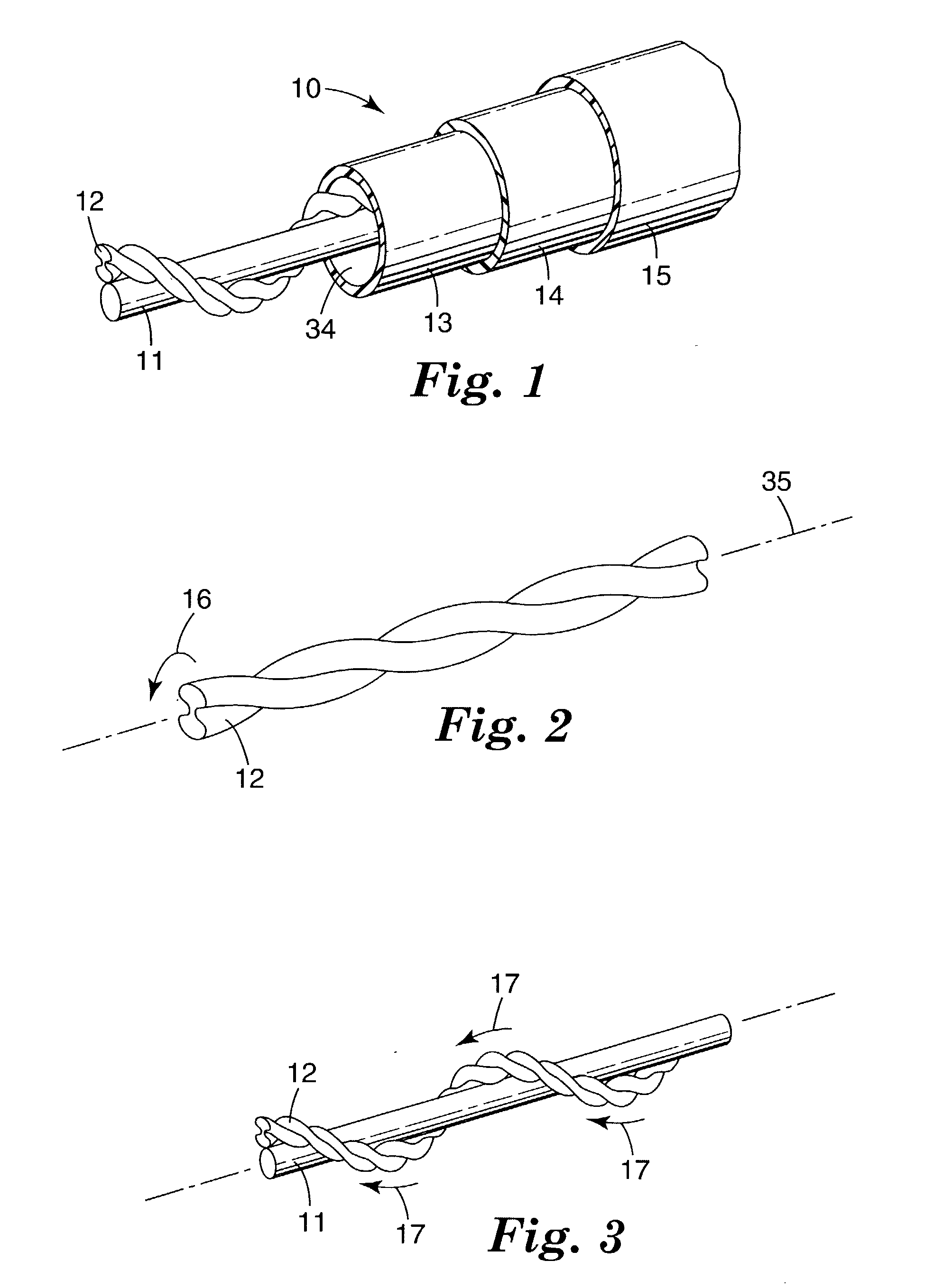
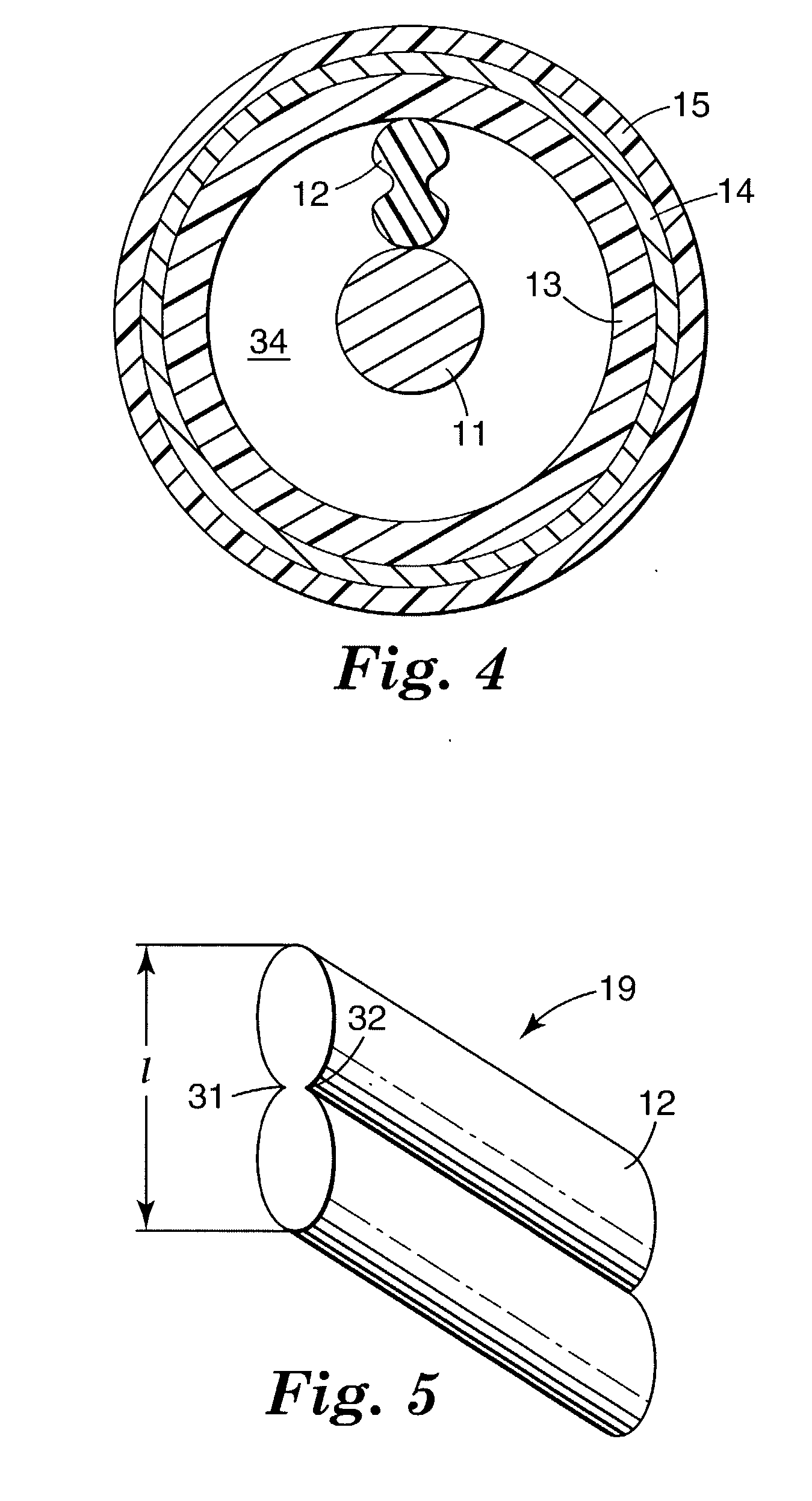
[0029] FIGS. 1 and 4 show an air core coaxial cable 10 constructed in accordance with the invention. Cable 10 has an inner conductor 11, and a solid core filament spacer 12 that is twisted around its own axis and then helically wound around inner conductor 11. Dielectric tube 13 is formed around spacer 12. Outer conductor or shield 14 is formed on top of tube 13, and an outer plastic jacket 15 is applied around shield 14.

[0030] As with all spacers of the first embodiment, spacer 12 in FIGS. 1 and 4 is formed with substantially less cross-sectional area than a spacer of circular cross-section with an equivalent spacing characteristic. Spacer 12 has a "dumbbell" profile; but its profile may alternatively have any of the "profiles" hereinafter specifically illustrated, or other "profiles" of equivalent nature which practitioners in the art can realize. Advantageously, spacer 12 is formed by extrusion, a process which is well-suited to creating numerous different "profiles".

[0031] The s...

second embodiment

[0041] If one or more strength members 48 are included in any the above-described embodiments, then in accordance with a further variation of the invention the spacer 12 instead of being a solid extrusion may consist of expanded materials of the type described below in the

[0042] A wide range of materials may be used to fabricate extruded spacers 12, including flouoropolymers such as perfluoroalkoxy (PFA) and fluorinated ethylene propylene (FEP); and polyolefins such as polyethylene (PE), polypropylene (PP) and polymethyl pentane. Of these, a preferred choice is PFA because of its low dielectric constant and dissipation factor.

[0043] By way of example, a 50 ohm coaxial cable constructed in accordance with the first embodiment of the invention consists of a silver-plated stranded copper inner conductor 11, an extruded dielectric spacer 12 of PFA material, a tube 13 of FEP material, an outer conductor 14 of silver-plated copper wire braid and an outer jacket 15 of FEP. Inner conductor ...


PUM


Abstract

The amount of air dielectric in air core coaxial and twinaxial cables is increased by spacer structures installed between the center conductor and the outer shield which have provision for air voids or pockets running lengthwise. The extra air space provides lower effective dielectric constant for the cable. In one embodiment, a single-element extruded spacer is formed with air cavities or voids that run continuously throughout the length of the spacer. Several spacer "profiles" or cross-sections are disclosed that place less solid dielectric mass in proximity to the center conductor. The result is a greater volume of air dielectric, and hence a lowered cable dielectric constant. In a further embodiment the spacer is a circular cross-sectioned element consisting of a central dielectric strength member surrounded with foamed material. Strength strands such as Kevlar(R) may be added to the spacer.

Description

[0001] This invention relates to air core coaxial and twinaxial cables; and more particularly to improved structures for spacing the inner conductor from the outer conductor or shield in these cable constructions to achieve a low-loss cable having increased signal propagation speed.[0002] Air core coaxial cables basically consist of an insulated signal conductor and a metallic outer shield separated from the inner conductor by a dielectric spacer. Air core twinaxial cables basically consist of two insulated signal conductors separated by dielectric spacers from a common metallic shield. In both designs, typically a core tube is included between each spacer and the surrounding metallic outer shield.[0003] For many coaxial and twinaxial cable applications, achieving high signal propagation speed with less susceptibility to signal loss and distortion is a critical requirement. Examples of such applications include low-loss UHF / microwave interconnect cable, wireless telephony base stati...

Claims


Application Information

Patent Timeline
IPC IPC(8): H01B11/18
CPCH01B11/1847
Inventor SPRINGER, DENIS D.LODER, HARRY A.
Owner 3M INNOVATIVE PROPERTIES CO
Why Eureka
Try Eureka