Stator support device and torque converter including the same

a technology of support device and torque converter, which is applied in the direction of fluid couplings, gearing, liquid fuel engines, etc., can solve the problems of increasing the axial length of the race, and the lubricant path leading to the interior of the torque converter cannot be surely provided in the presence of the support member, so as to avoid or suppress the reduction of the lifetime of the torque converter due to poor lubrication, the effect of further reducing the axial length of the stator upon assembling

Active Publication Date: 2004-04-22
TOYOTA JIDOSHA KK
View PDF4 Cites 16 Cited by
  • Summary
  • Abstract
  • Description
  • Claims
  • Application Information

AI Technical Summary

Benefits of technology

0074] In the support device of the stator 220 according to the present embodiment, the thickness of the thrust bearing race 520 disposed at one end face of the one-way clutch outer race 320 is made smaller than that of the thrust bearing race 530 disposed at the other end face, so that the axial length of the stator upon assembling can be further reduced. Also, the arrangement of the stator support device of this embodiment makes it possible to lubricate the back face of the lock-up piston 112 so as to cool the clutch lining 108, and therefore an otherwise possible reduction in the lifetime of the torque converter due to poor lubrication can be avoided or suppressed.
0075] In the stator support devices according to the first through third embodiments of the invention as described above in detail, the OWC outer race bears the load applied to the thrust bearing, via the thrust bearing race disposed at an (or each) end face of the outer race. Since the rigidity of the OWC outer race is high enough to bear or sustain the load, a reduction in the lifetime of the thrust bearing can be avoided or suppressed. In addition, the thickness of the thrust bearing race can be minimized, and the axial length of the stator support device can be reduced accordingly.
0076] Furthermore, the spacing between the OWC outer race and the OWC inner race can be appropriately maintained by the OWC end bearing, oscillations occurring du

Problems solved by technology

In the stator device disclosed in JP-A-2001-323985, since the thrust bearing race needs to receive a load from the thrust bearing and transmit the load to the stator, the thrust bearing race is required to have suff

Method used


Image

  • Stator support device and torque converter including the same
  • Stator support device and torque converter including the same
  • Stator support device and torque converter including the same

Examples


first embodiment

[0038] First Embodiment

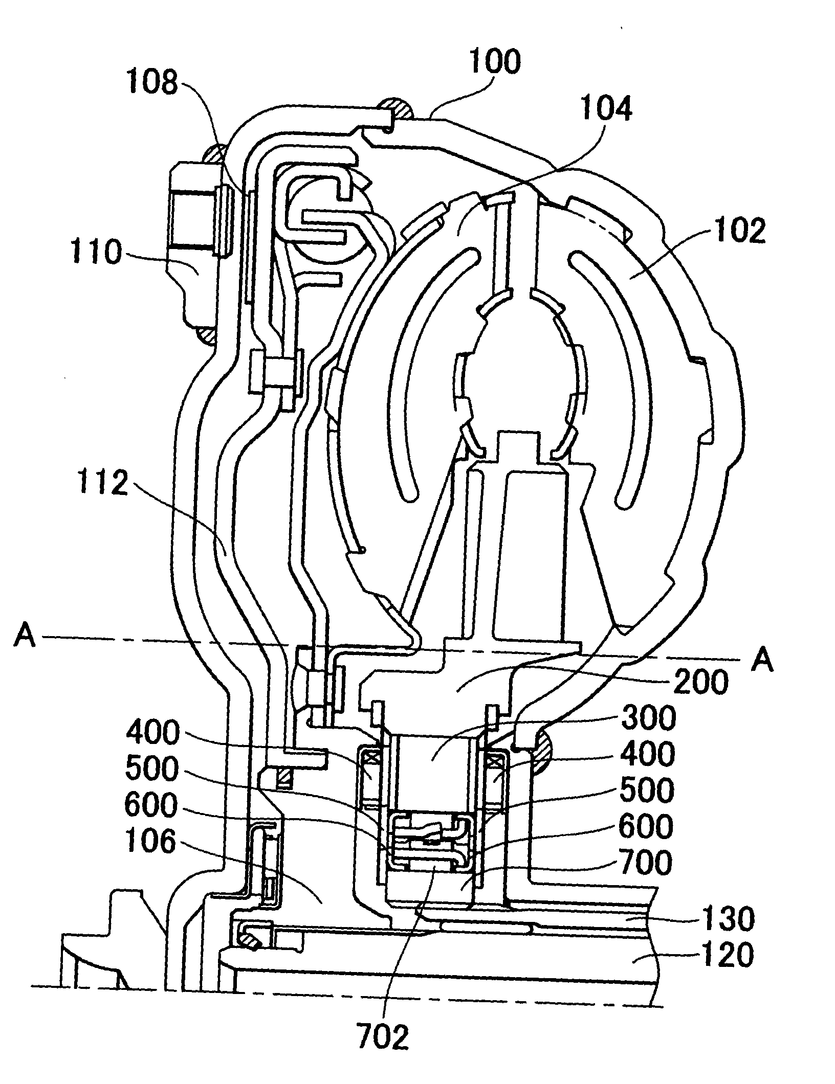
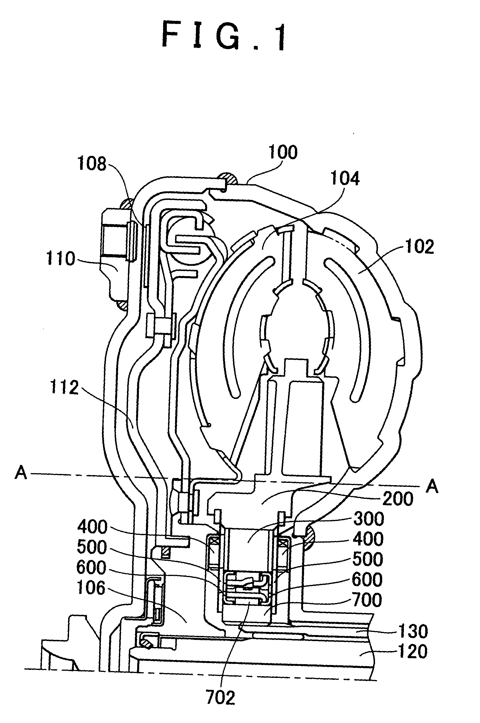
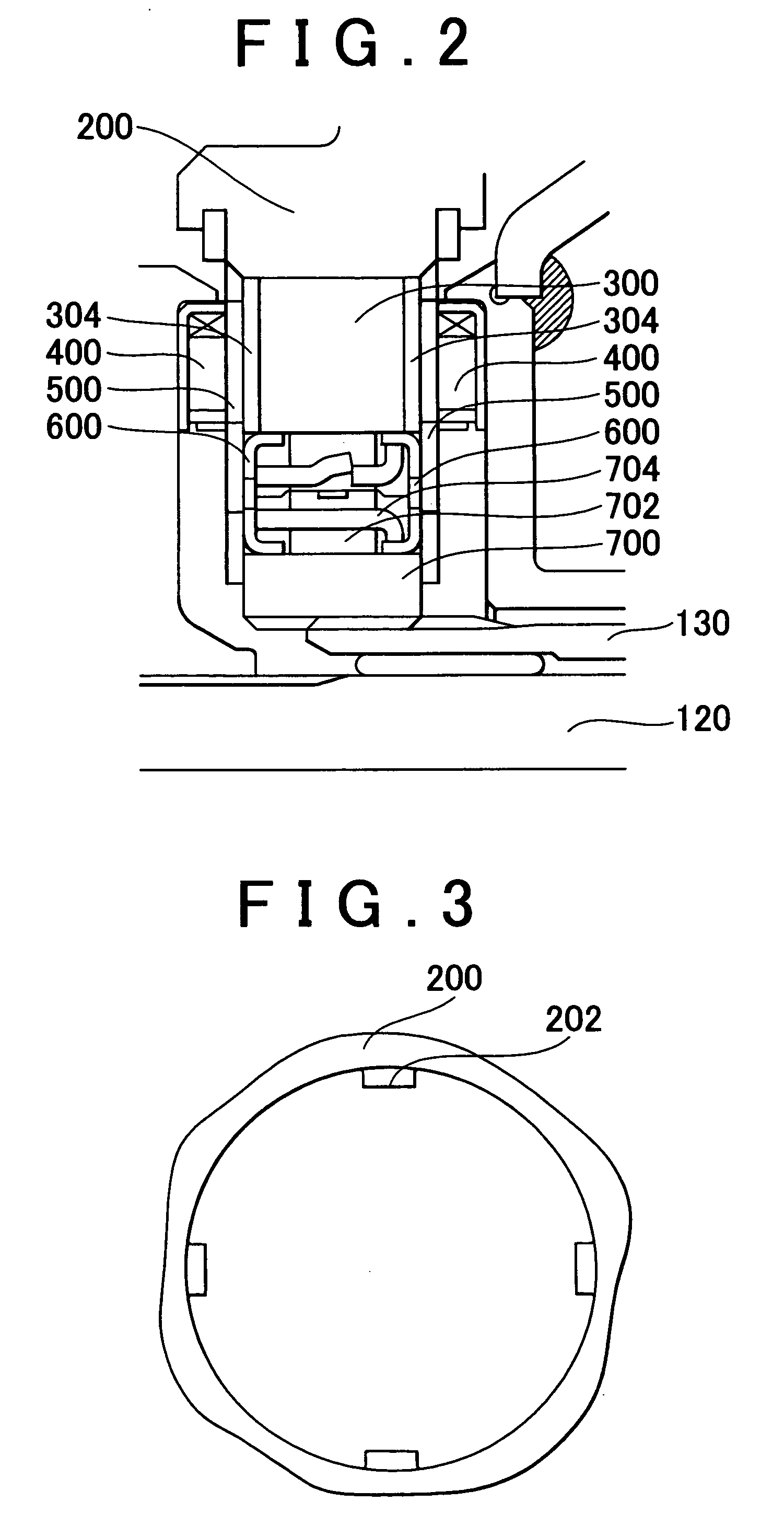
[0039] Referring first to FIG. 1, the construction of a torque converter 100 including a stator support device according to a first embodiment of the invention will be described. The torque converter 100 includes a pump impeller 102, a turbine runner 104 and a stator 200. A one-way clutch (hereinafter referred to as "OWC") composed mainly of a one-way clutch outer race 300, a one-way clutch inner race 700 and sprags 702 is disposed at the inner circumference of the stator 200. The stator 200 is attached to a transmission stationary shaft 130 via the thus constructed OWC, such that the stator 200 is allowed to rotate only in one direction.

[0040] The pump impeller 102 is attached to an engine output shaft 110, and serves to convert the power of the engine (not shown) to into energy in the form of flow of working oil in the torque converter 100. The turbine runner 104 converts this energy into rotational energy, and rotates a transmission input shaft 120 to which...

second embodiment

[0055] Second Embodiment

[0056] Hereinafter, a stator support device according to a second embodiment of the invention will be described. The construction of the stator support device according to this embodiment is difference from that of the first embodiment as described above in that the invention is applied to only one end face of the one-way clutch.

[0057] Referring to FIG. 7, the construction of the stator support device according to the second embodiment will be described. The structure of the torque converter including the pump impeller, turbine runner and stator is identical with the structure of the torque converter 100 (shown in a portion of FIG. 1 located above the A-A line) according to the first embodiment as described above, and thus will not be repeatedly described herein. Also, the positional relationship among OWC outer race 310, OWC inner race 710, sprags 702 and cage 704 is the same as that in the structure of the stator support device according to the first embodi...

third embodiment

[0068] Third Embodiment

[0069] Hereinafter, a stator support device according to a third embodiment of the invention will be described. The construction of the stator support device according to the third embodiment is different from those of the first and second embodiments in that thrust bearing races having different thicknesses are disposed at respective end faces of the OWC outer race.

[0070] Referring to FIG. 11, the construction of the stator support device according to the third embodiment will be described. The structure of the torque converter including the pump impeller, turbine runner and the stator is identical with the structure of the torque converter 100 (shown in a portion of FIG. 1 located above the A-A line) according to the first embodiment as described above, and thus will not be repeatedly described herein. Also, the positional relationship among OWC outer race 320, OWC inner race 720, sprags 702 and cage 704 is the same as that in the structure of the stator sup...


PUM


Abstract

A stator support device for supporting a stator of a torque converter includes a one-way coupling device including an outer race disposed radially inwardly of the stator, and an inner race disposed radially outwardly of a rotation axis of the torque converter, an end bearing that holds a spacing between the outer race and the inner race, a thrust bearing race disposed adjacent to an end face of the outer race and arranged to restrict movements of the end bearing in a direction of the rotation axis, and a thrust bearing disposed at a transfer surface of the thrust bearing race and adapted to bear a load applied to the one-way coupling device.

Description

INCORPORATION BY REFERENCE[0001] The disclosure of Japanese Patent Application No. 2002-300209 filed on Oct. 15, 2002, including the specification, drawings and abstract, is incorporated herein by reference in its entirety.[0002] 1. Field of the Invention[0003] The invention relates to a torque converter installed on a vehicle, and, more particularly, to a technique for supporting a stator of the torque converter.[0004] 2. Description of Related Art[0005] A torque converter for multiplying torque generated by a power source and transmitting the torque to the next power transmission stage includes an impeller called "stator". The stator is mounted on a rotary shaft via a one-way clutch, and is operable to direct flow of working oil from a turbine runner toward an inlet of a pump impeller.[0006] FIG. 13 shows a torque converter 1000 including a conventional support device of a stator 2000. Referring to FIG. 13, an aluminum washer 650 holds or maintains the spacing between a one-way cl...

Claims


Application Information

Patent Timeline
IPC IPC(8): F16D33/00F16H41/24F16D33/18F16H41/30
CPCF16D33/00F16H2041/246F16H41/24F16D33/18
Inventor OCHI, TORUTAKEUCHI, HIROAKIYASUDA, YUJI
Owner TOYOTA JIDOSHA KK
Why Eureka
Try Eureka