Optical interference filter having parallel phase control elements

a phase control element and optical interference technology, applied in the field of optical interference filters having parallel phase control elements, can solve the problems of reducing the overall efficiency and accuracy of an optical communication system, limiting the number of channels employable over a given wavelength domain, and substantially limiting the narrowest channel spacing achievabl

Inactive Publication Date: 2004-04-29
EXCELITAS TECH
View PDF35 Cites 21 Cited by
  • Summary
  • Abstract
  • Description
  • Claims
  • Application Information

AI Technical Summary

Problems solved by technology

Although wavelength division multiplexing provides a simple, effective and inexpensive way of increasing transmission capacity, the number of channels employable over a given wavelength domain is limited by cross talk between transmission channels.
As understood by those skilled in the art, cross talk degrades the overall efficiency and accuracy of an optical communication system and substantially limits the narrowest channel spacing achievable.
Although the optical filters in U.S. Pat. No. 6,304,689 are reported to provide spectral characteristics beneficial for multiplexing and demultiplexing applications, the disclosed design is susceptible to substantial problems arising from structural limitations inherent to fabrication of devices employing an orthogonal interferometer geometry.
First, the orthogonal arrangement of the prior art is susceptible to optical path length mismatch between the two legs of the Michelson or Tyman-Green interferometer.
Optical path length mismatch is a deviation from the selected optical path lengths through each leg of the interferometer, which is introduced by fabrication errors.
Mismatch errors result in substantial aberrations in the frequency, bandwidth and shape of the transmission bands because it is the selected difference in the optical path lengths of first and second beam components that establishes the net optical interference resulting upon beam recombination.
Specifically, optical path length mismatch leads to substantial deviations from the desired square-wave shaped transmission bands of optical interleavers, which reduces light throughput and increases cross talk.
Indeed, the piece-to-piece optical path length variation observed in optical filters having an orthogonal interferometer arrangement necessitates the use of optical path length compensation schemes, which add considerably to the complexity and cost of prior art interleavers.
Second, the optical configuration disclosed in U.S. Pat. No. 6,304,689 is also vulnerable to angular mismatch in the combination of the first and second beam components corresponding to each leg of the interferometer.
This sensitivity arises from deviations in the relative positions of the cube-type beam splitter and each orthogonal leg of the interferometer, namely pyramidal error.
In addition, susceptibility to angular mismatch derives from difficulties in fabricating a beam splitter in which the partially reflective surface is positioned at an angle precisely 45 degrees from the internal ends of each orthogonal leg of the interferometer.
Angular mismatch causes poor vertical and horizontal beam recombination, which results in a substantial degradation in interleaver performance.
Specifically, angular mismatch leads to high insertion loss, which decreases transmission of light having frequencies corresponding to the transmission bands and increases unwanted transmission of light having frequencies outside the transmission bands.
High insertion loss, therefore, results in poor light throughput and increased cross talk.
Although the dual GT etalon interleaver design is reported to provide improved transmission and channel stability with respect to temperature variations, the design employs an orthogonal interferometer geometry highly susceptible optical path length mismatch and poor angular recombination.
The optical arrangements described, however, are limited to orthogonal interferometer geometries, which are susceptible to optical path length mismatch and poor angular recombination.
While the methods and device components described in U.S. Pat. Nos. 6,725,322 and 6,386,718 are reported to provide methods of compensating for fabrication related optical path length variations, the designs add substantially to the complexity, cost and difficulty of fabrication of interferometric optical interleavers.
Horizontal angular recombination errors arise from a mismatch of the optical angles which establish the optical paths of first and second beam components.
Structural limitations in fabricating orthogonal interferometer optical arrangements, however, result in substantial deviations in these angles of greater than 20 arcseconds.
Decreasing the number of independent variables relating to the position of the phase control elements reduces the observed variations in optical path length through first and second phase control elements and decreases the overall design complexity of the optical path length-matching scheme.
Phase manipulation may be achieved by introducing an additional optical path length, dividing a beam into subcomponents, causing optical interference or other methods well known in the art.
If uncorrected, the loss of linear polarization results in incomplete interference upon recombination of first and second beam component.

Method used


Image

  • Optical interference filter having parallel phase control elements
  • Optical interference filter having parallel phase control elements
  • Optical interference filter having parallel phase control elements

Examples


example 1

Optical Inteleaver Frequency Matched to Even or Odd Transmission Channels of a Frequency Standard with 50 GHz Transmission Channels having a Parallel GT Etalon Phase Control Element and an Air Gap Phase Control Element

[0136] The ability of optical interference filters of the present invention to function as a channel dropping or channel adding optical interleaver was evaluated by numerical modeling methods. Specifically, it is a goal of the present invention to provide optical interference filters capable of isolating either even or odd transmission channels of a given frequency standard having narrowly spaced transmission channels. Further, it is a goal of the present invention to provide optical interference filters capable of transmitting substantially all light having frequencies corresponding to a selected transmission channel or series of transmission channels and capable of substantially preventing transmission of all light having frequencies outside a selected transmission b...

example 2

Method of Fabricating Optical Interference Filters having a Parallel Interferometer Geometry

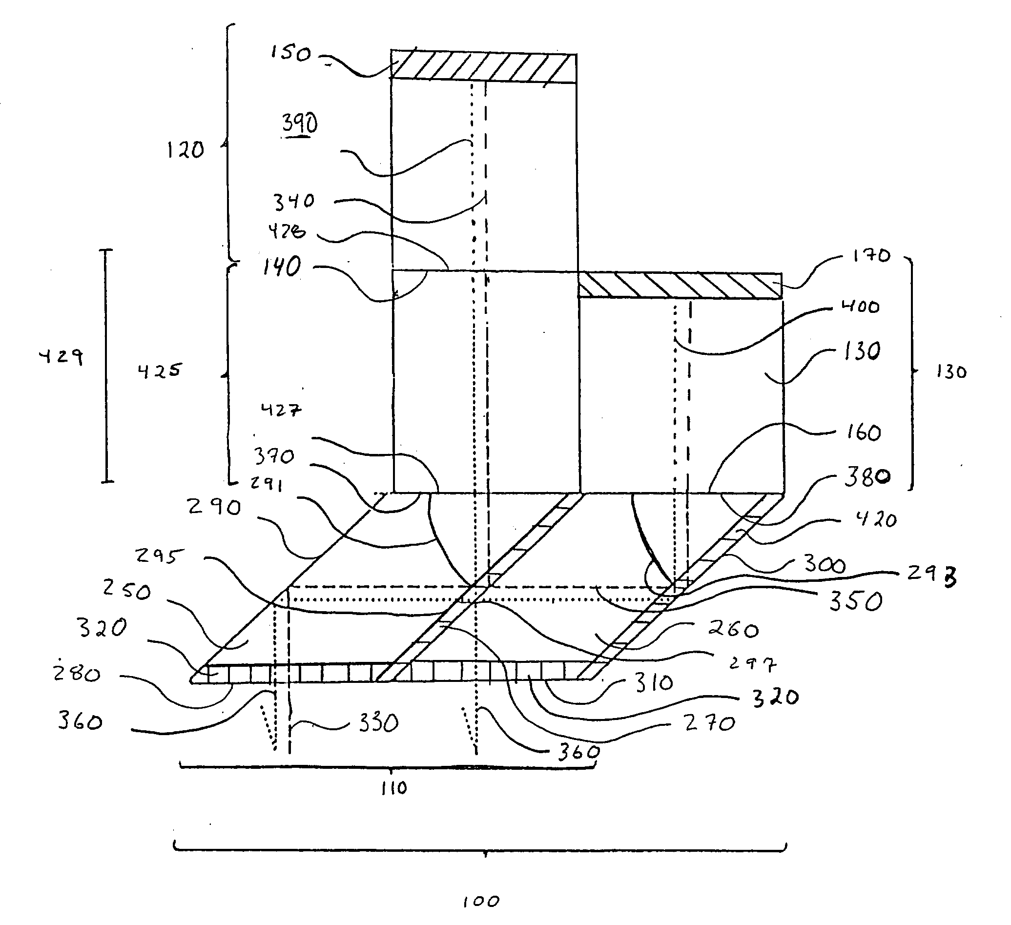
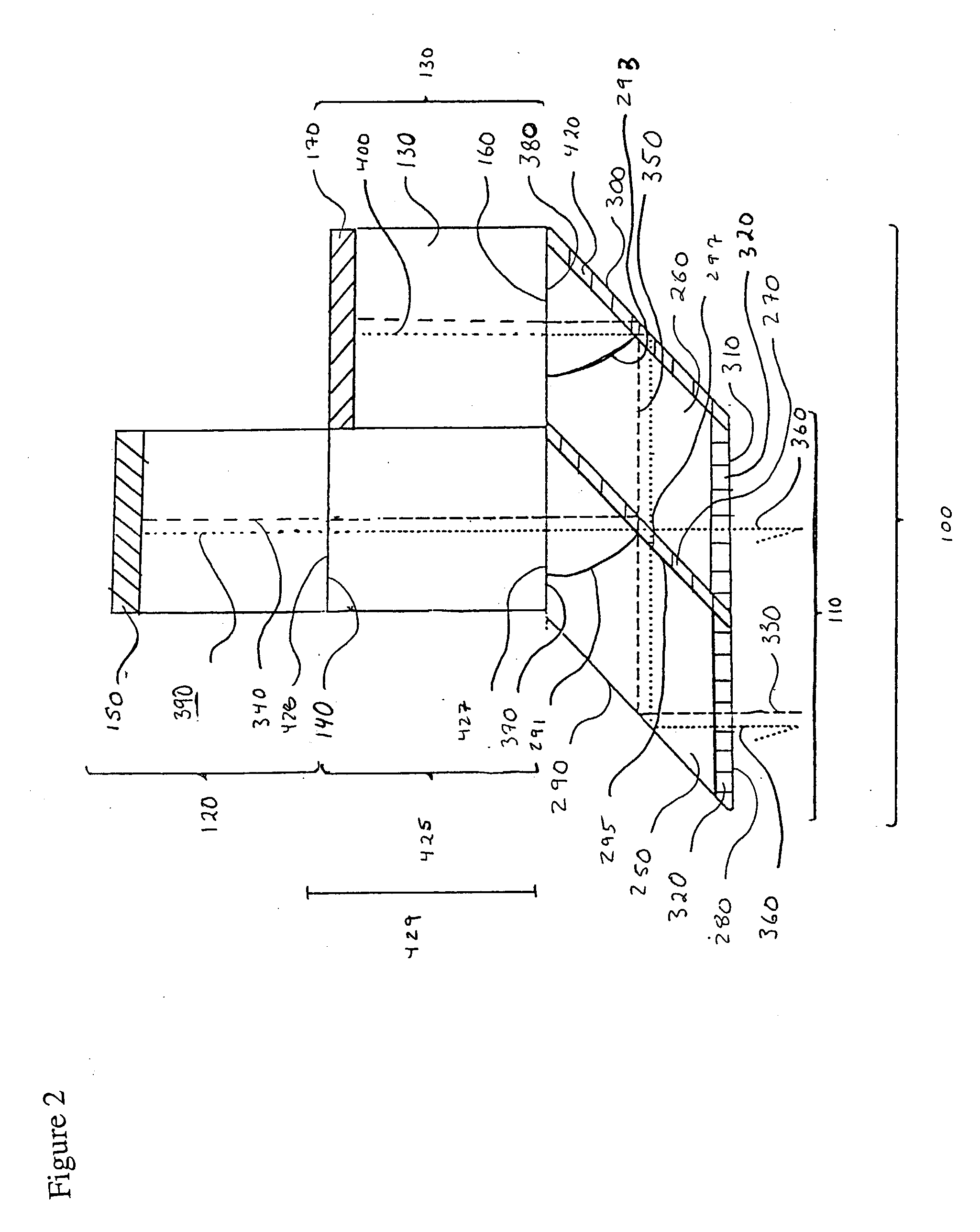
[0142] The present invention includes optical interference filters that can be manufactured by convention fabrication methods with reduced vertical and horizontal recombination distortion. In addition, the optical interference filters of the present invention are able to be manufactured via conventional fabrication methods with a great degree of precision with respect to the selected optical path length of the first beam component and the selected optical path length of the second beam component. The methods described below correspond to preferred methods of making the optical interference filters illustrated in FIGS. 2, 3 and 4.

[0143] A preferred method of making a beam splitter having a parallel reflector geometry comprises the steps of: (1) simultaneously polishing the reflective surface and first prism coupling surface of first prism element to achieve ultra flat and ultra smooth, substan...


PUM


Abstract

The invention relates generally to optical interference filters and interferometers. Methods, devices and device components are presented for separating closely spaced optical channels with minimized cross talk. The invention provides optical interference filters having parallel phase control elements which efficiently transmit light of a selected optical channel or a plurality of selected channels with decreased light loss, particularly decreased insertion loss. An exemplary interference filter of the present invention provides minimized vertical and horizontal recombination error and improved optical path length matching. The invention further provides methods of fabricating optical interference filters with improved piece-to-piece reproducibility. The methods, devices and device components provided herein are particularly well-suited for combining or separating closely spaced optical signals corresponding to transmission channels of a selected frequency standard, such as the International Telecommunication Union frequency standard.

Description

[0001] This invention relates generally to optical interferometry. In particular, the invention relates to methods, devices and device components employing interferometers and optical interference filters for processing optical signals. Optical interleavers having parallel phase control elements are described, which are particularly useful for wavelength division multiplexing and demultiplexing applications.BACKGROUND OF INVENTION[0002] Optical telecommunication systems are capable of efficient and accurate signaling at extremely high rates ranging several mega-bits per second to several tens of giga-bits per second. In addition, optical signaling techniques have significant advantages over non-optical communication methods, such as coaxial cable, copper wire and microwave transmission techniques, which include lower propagation loss, higher channeling capacity and insusceptibility to electromagnetic interference. As a result of these benefits, optical communication systems are prev...

Claims


Application Information

Patent Timeline
Patent Type & Authority Applications(United States)
IPC IPC(8): G02B5/28G02B27/14
CPCG02B5/281G02B27/144G02B27/142G02B27/1073
Inventor THOMPSON, JAMES TRISTAN
Owner EXCELITAS TECH
Why Eureka
Try Eureka