Energy saving vacuum system for particle, mist, and fume collection

a vacuum system and energy saving technology, applied in the field of gate valves, can solve the problems of toxic to the environment, harmful to exposed workers, and generating fumes or mist during industrial production, and achieve the effects of saving a higher amount of energy, high ratio leverage, and reliable operation

Active Publication Date: 2004-05-20
LITOMISKY IVAN +2
View PDF7 Cites 43 Cited by
  • Summary
  • Abstract
  • Description
  • Claims
  • Application Information

AI Technical Summary

Benefits of technology

0029] It is another object of the present invention to provide a gate valve that is self-cleaning and reliable.
0030] It is yet another object of the present invention to provide a gate valve that is toothed about its exterior for engagement by a gear for high ratio leverage and reliable operation.
0031] It is another object of the present invention to regulat...

Problems solved by technology

Additionally, fumes or mist may be generated during industrial production, such as the lead fumes generated during the production of different types of batteries.
Such fumes can be harmful to exposed workers and toxic to the environment.
The sawdust and/or metal shavings that collect in the workshop can become dangerous.
The dust or micro fine metal particles may become airborne and inhaled deeply into the lungs of persons in the general vicinity, possibly causing injury and/or disease.
Additionally, thick suspensions of dust become fire or explosi...

Method used


Image

  • Energy saving vacuum system for particle, mist, and fume collection
  • Energy saving vacuum system for particle, mist, and fume collection
  • Energy saving vacuum system for particle, mist, and fume collection

Examples


Embodiment Construction

)

[0055] The detailed description set forth below in connection with the appended drawings is intended as a description of presently-preferred embodiments of the invention and is not intended to represent the only forms in which the present invention may be constructed and / or utilized. The description sets forth the functions and the sequence of steps for constructing and operating the invention in connection with the illustrated embodiments. However, it is to be understood that the same or equivalent functions and sequences may be accomplished by different embodiments that are also intended to be encompassed within the spirit and scope of the invention.

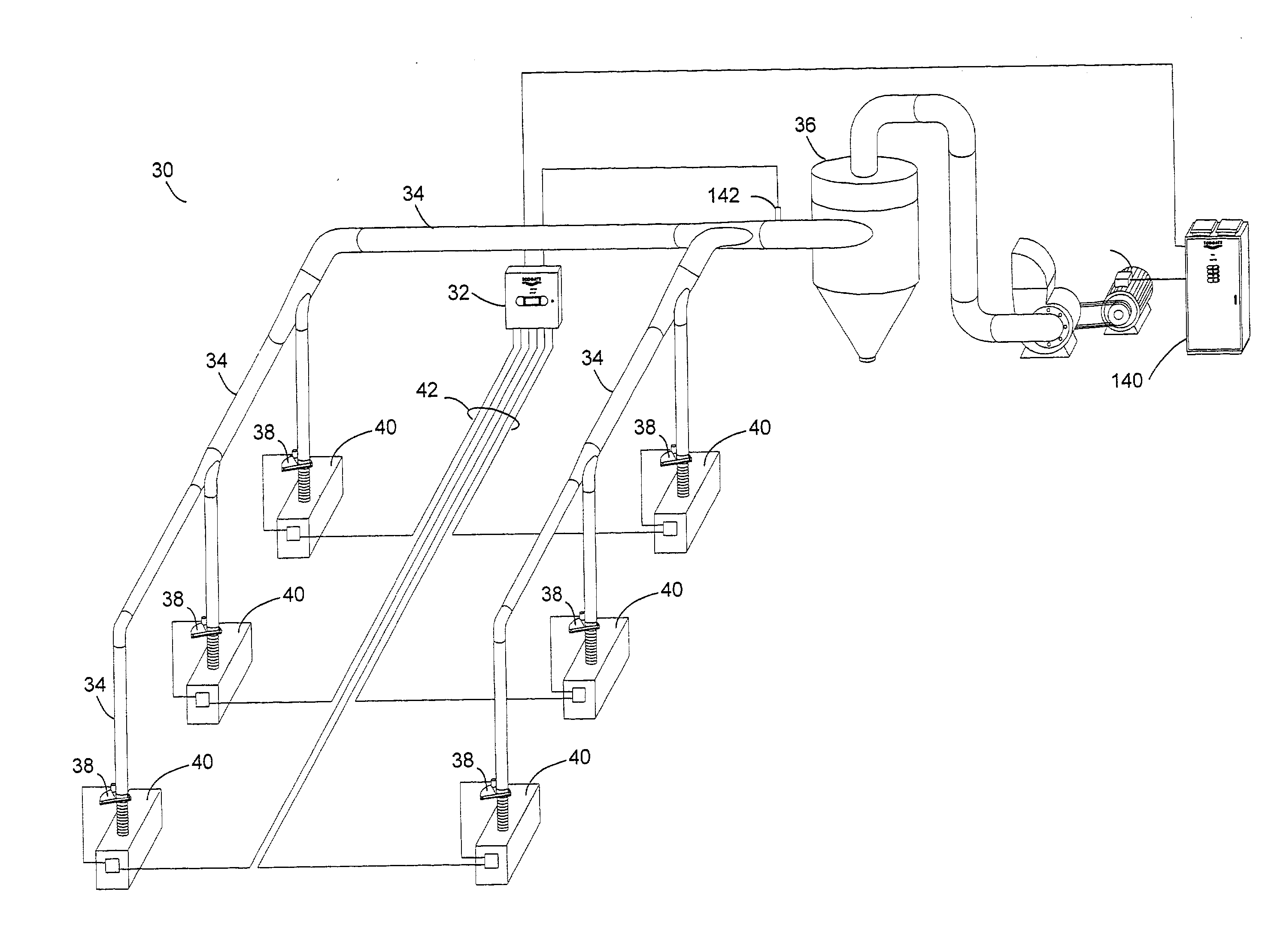
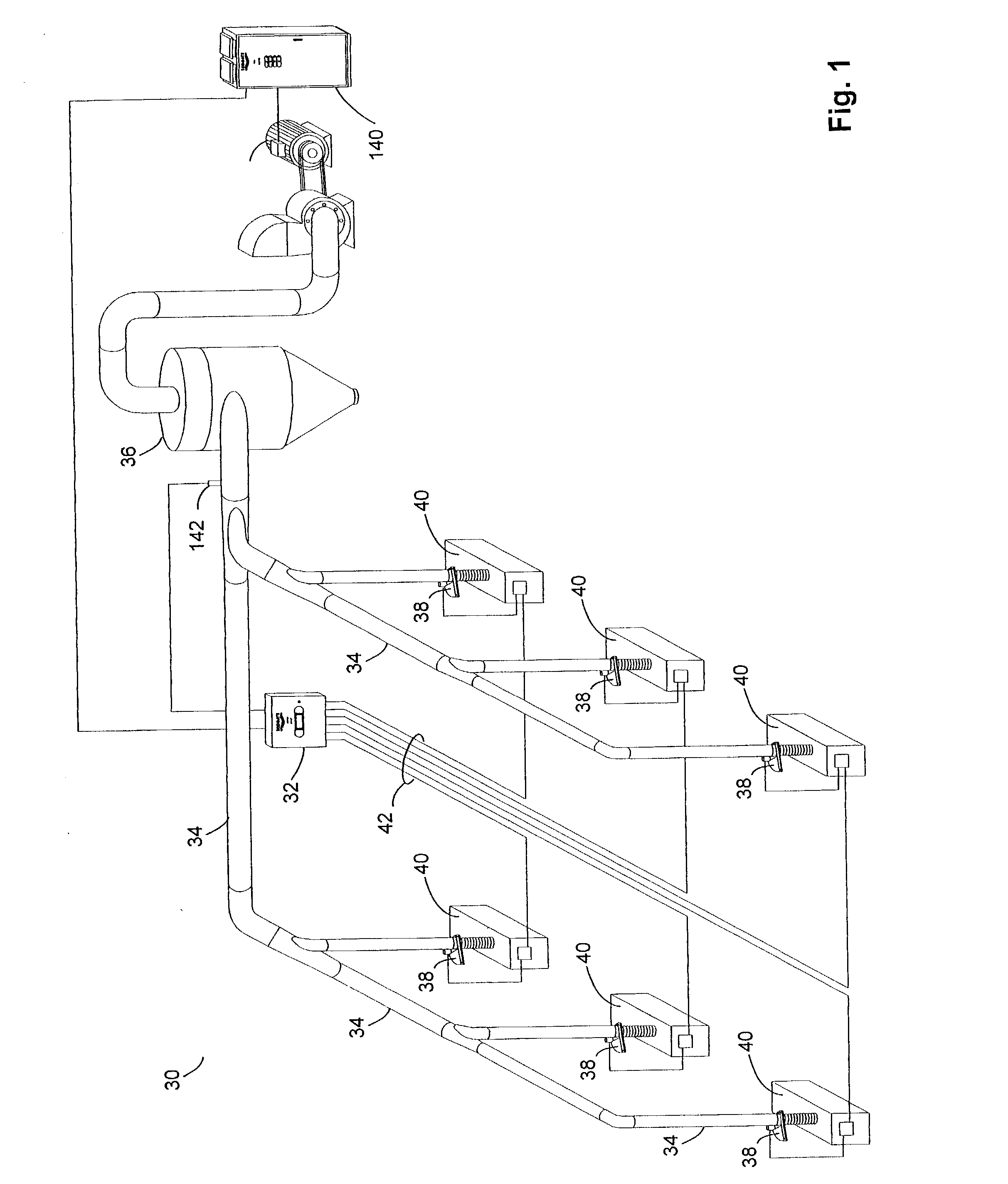
[0056] The present invention resides in a dust collection system for machine shops and the like that require the collection of dust generated by machining and woodworking processes. As a saw or the like operates, the work piece upon which it acts may give rise to dust, shavings, filings, or the like during the machining or wood workin...


PUM

PropertyMeasurementUnit
Lengthaaaaaaaaaa
Diameteraaaaaaaaaa
Diameteraaaaaaaaaa

Abstract

An improved energy-efficient vacuum system for machine shop dust, particulate matter, and the like. Blast gates, including large-diameter blast gates, control the flow of vacuum generated by a dust collector to individual machines that may or may not accommodate vacuum ductwork and the like. The blast gate has a rotating blade inside a chassis with a DC motor effectively using a slip clutch, an increased current feedback system, a biasing-spring assembly or otherwise to limit the rotation driving of the rotating blade. In one embodiment, the blast gate blade bears teeth about its perimeter. The DC motor engages the perimeter blade teeth with a gear. Greater mechanical advantage is achieved over the blast gate blade and less torque arises in contrast to a driving system located at the blade's central pivot point. Additionally, sensing apparatus or system calculation allow the dust collecting vacuum system to operate in an energy-efficient manner. By supplying only the vacuum needed to collect present dust, energy is saved in comparison with a dust collection system operating continuously at full capacity.

Description

[0001] 1. Field of the Invention[0002] This invention relates to gate valves used in machine shops that serve to control the flow of suction in collecting sawdust, mill filings and the like as well as mist and fume collection and more particularly to an advanced electric gate valve and accompanying system allowing the efficient operation of vacuum collection of dust and filings resulting in significant energy savings and noise reduction.[0003] 2. Description of the Related Art[0004] The entirety of U.S. Pat. No. 6,012,199 issued Jan. 11, 2000 is incorporated herein by this reference thereto.[0005] In machine shops, woodworking shops, and the like, work pieces are milled, lathed, drilled, formed, etc. to achieve the ends of the craft. In altering the structure of the work piece, dust, filings and / or tailings are created. For example, when sawing a piece of wood, sawdust will collect adjacent the area of the saw blade. Likewise, for lathing or milling processes, shavings or tailings f...

Claims


Application Information

Patent Timeline
IPC IPC(8): A47L5/38A47L9/28B23D59/00B23Q11/00
CPCA47L5/38A47L9/2805A47L9/2842A47L9/2857B23Q11/0046A47L9/2889A47L9/2894B23D59/006A47L9/2868
Inventor LITOMISKY, IVANLITOMISKY, PETRLITOMISKY, ALES
Owner LITOMISKY IVAN
Why Eureka
Try Eureka