Imaging lens device and digital camera having the imaging lens device
a technology of imaging lens and digital camera, which is applied in the field of imaging lens device, can solve the problems of significant affecting the optical performance, the inability to further bend the optical axis of this optical system, and the size of the camera body
Inactive Publication Date: 2004-05-20
MINOLTA CO LTD
View PDF18 Cites 65 Cited by
- Summary
- Abstract
- Description
- Claims
- Application Information
AI Technical Summary
Benefits of technology
[0011] Another object of the present invention is to provide a novel imaging lens device having a zoom lens system which lens device is small in size, is high in zoom magnification and realizes high image quality.
Problems solved by technology
However, in U.S. Pat. No. 5,448,319 and European Patent No. 0906587, although size reduction is attained by bending the optical path, the disclosed optical systems are fixed focal length lens systems and not high-zoom-magnification zoom lens systems satisfying high image quality.
However, it is impossible to further bend the optical axis of this optical system.
When the overall length of the optical system is forcibly reduced, the sensitivity to errors increases, so that manufacture errors significantly affect the optical performance.
When the overall length of the optical system is reduced by increasing the number of lens units that are movable during zooming, the lens barrel structure is complicated, so that the camera body is increased in size.
This is undesirable from the viewpoint of size reduction.
When the lower limit of the condition (1) is exceeded, the axial distance between the aperture stop and the second reflecting surface is too short, so that it is difficult to bend the optical axis.
When the lower limit of the condition (2) is exceeded, the focal length (absolute value) of the lens unit situated on the object side of the first reflecting surface is too small, so that distortion, particularly negative distortion on the wide-angle side is considerable.
Consequently, it is difficult to ensure excellent optical performance.
This is undesirable from the viewpoint of size reduction.
Method used
View moreImage
Smart ImageViewing Examples

Examples
Embodiment Construction
1.063 4.251 Example 2 1.058 4.275 Example 3 1.073 4.261 Example 4 2.340 6.053
[0120]
24TABLE 6 Focusing data Focusing Unit: Fourth Lens Unit (Gr4) Movement Direction: Toward the Object Shooting Distance (from Object Point to Image Plane): Example 1.about.3 D = 0.37(m), Example 4 D = 0.67(m) Movement Distance of Focusing Unit (mm) W M T Example 1 0.096 0.668 1.692 Example 2 0.136 0.840 2.158 Example 3 0.087 0.700 1.753 Example 4 0.065 0.446 1.130
Login to View More PUM
 Abstract
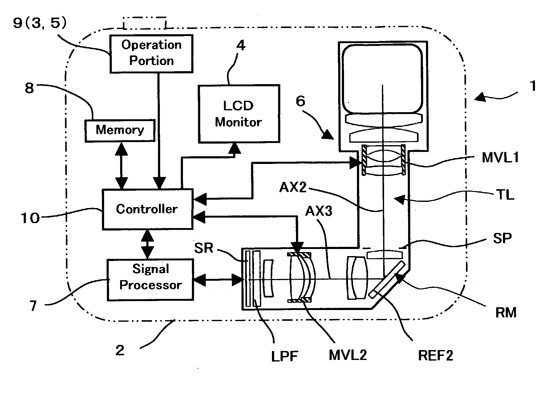
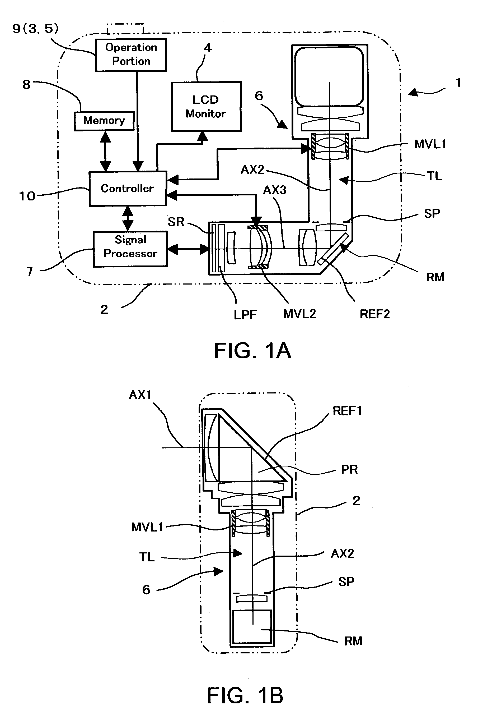
Imaging lens device has a zoom lens system and an image sensor. The zoom lens system has a first reflecting surface, a first movable lens unit, an aperture stop, a second reflecting surface, a second movable lens unit. A first reflecting surface bends a first optical axis which is an incident optical axis of the zoom lens system 90 degrees into a second optical axis. A second reflecting surface bends the second optical axis 90 degrees into a third optical axis. The first optical axis, the second optical axis and the third optical axis are mutually perpendicular. The first movable lens unit and the aperture stop are disposed on the second optical axis. The second movable lens unit is disposed on the third optical axis. During zooming, the first and second reflecting surfaces and the aperture stop are stationary; the first and second movable lens units are moved, respectively.
Description
[0001] This application is based on the application No. 2002-336879 filed in Japan Nov. 20, 2002, the entire content of which is hereby incorporated by reference.[0002] 1. Field of the Invention[0003] The present invention relates to an imaging lens device. More specifically, the present invention relates to an imaging lens device provided with a compact and high-zoom-magnification zoom lens system suitable for digital input and output apparatuses such as digital cameras and a cameras incorporated in or externally attached to a personal computer, a mobile computer, a mobile telephone or the like. Moreover, the present invention relates to digital input and output apparatuses having an imaging lens device provided with a compact and high-zoom-magnification zoom lens system.[0004] 2. Description of the Related Art[0005] In recent years, with the spread of personal computers and the like, digital still cameras, digital video cameras and the like (hereinafter, referred to as digital cam...
Claims
Login to View More Application Information
Patent Timeline
 Patent Type & Authority Applications(United States)
IPC IPC(8): G02B15/167G02B13/00G02B13/18G02B15/16G02B17/08G03B17/17H04N5/225H04N5/232
CPCG02B13/004G02B13/0045G02B13/006H04N5/2254G02B13/009G02B15/161G02B13/0065G02B15/142
Inventor IWASAWA, YOSHITOMATSUI, KAZUAKIHARA, YOSHIHIROKOSAKA, AKIRAUEDA, SADANOBUYOKOTA, SATOSHI
Owner MINOLTA CO LTD
Features
- R&D
- Intellectual Property
- Life Sciences
- Materials
- Tech Scout
- Unparalleled Data Quality
- Higher Quality Content
- 60% Fewer Hallucinations
Learn More Browse by: Latest US Patents, China's latest patents, Technical Efficacy Thesaurus, Application Domain, Technology Topic, Popular Technical Reports.
© 2025 PatSnap. All rights reserved.Legal|Privacy policy|Modern Slavery Act Transparency Statement|Sitemap|About US| Contact US: help@patsnap.com