Particle-optical apparatus, electron microscopy system and electron lithography system

a technology of electron microscopy and electron lithography, which is applied in the field of particleoptical apparatus, electron microscopy system and electron lithography system, can solve the problems of imposing limitations on the configuration of the beam manipulating field, affecting the mechanical precision of the source member, and affecting the production efficiency of source members

Inactive Publication Date: 2004-06-03
CARL ZEISS SMT GMBH
View PDF7 Cites 31 Cited by
  • Summary
  • Abstract
  • Description
  • Claims
  • Application Information

AI Technical Summary

Problems solved by technology

This imposes limitations on the configuration of the fields manipulating the beam.
The limitations are due to limits in respect of the mechanical precision in the manufacture of the source members as well as in respect of the mechanically feasible geometries of the field source members.
As the quadrupole field to be formed for generating the round lens effect is

Method used


Image

  • Particle-optical apparatus, electron microscopy system and electron lithography system
  • Particle-optical apparatus, electron microscopy system and electron lithography system
  • Particle-optical apparatus, electron microscopy system and electron lithography system

Examples


Embodiment Construction

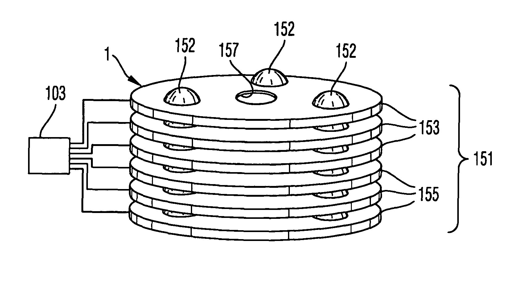
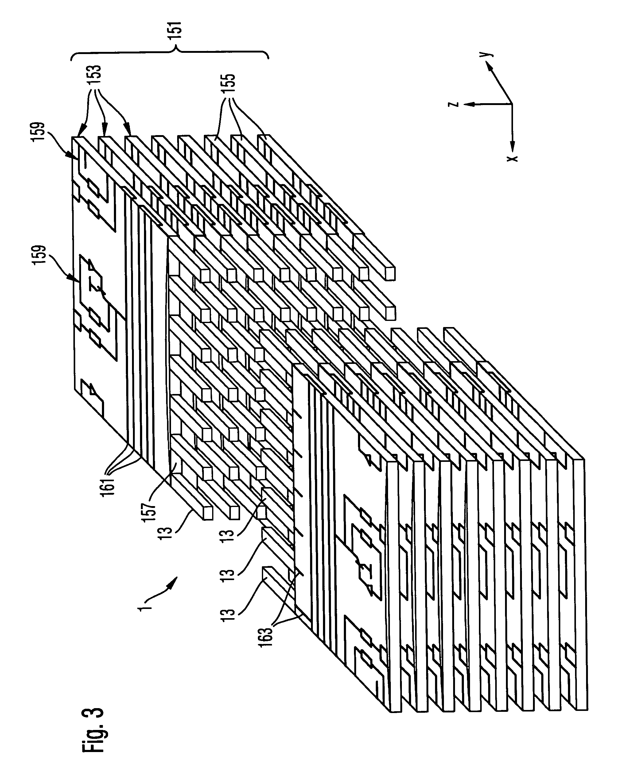
[0050] FIG. 3 shows a particle-optical apparatus 1 according to the invention in perspective, partly cut-open view. The apparatus 1 comprises a stack 151 of a plurality of lens assemblies 153 which are disposed spaced apart from each other in the z-direction. Each lens assembly comprises of a plate 155 which delimits an aperture 157 which is elongated in the x-direction. Finger electrodes 13 project into the aperture 157 in the y-direction. The finger electrodes 13 are disposed in a row in the x-direction, spaced apart and insulated from each other. One row of finger electrodes 13 is provided on each side of the aperture 157. Each finger electrode of the one row is disposed opposite in the y-direction to a corresponding finger electrode of the other row. It should be noted that references to x-direction, y-direction, z-direction, etc., herein are merely for convenience and should not be considered as limiting the scope of the invention in any way.

[0051] Moreover, the plate 155 carri...


PUM


Abstract

A particle-optical apparatus is provided for directing a beam of charged particles on an object plane or to image the object plane with the beam onto an image plane or intermediate image plane. The apparatus comprises a stack of lens assemblies which are disposed in beam direction at a fixed distances spaced apart from which other and are controllable for providing successively adjustable deflection fields for a beam traversing the stack. Each lens assembly provides at least one field source member for a magnetic or electric field. In particular, two rows of a plurality of field source members per lens assembly can be provided.

Description

[0001] This application is based upon DE 102 37 141.5 filed on Aug. 13, 2002, and DE 102 37 297.7 filed on Aug. 14, 2003, the entire contents of each of which are incorporated herein by reference.[0002] 1. Field of the Invention[0003] The invention relates to a particle-optical apparatus, an electron microscopy system and an electron lithography system.[0004] 2. Brief Description of Related Art[0005] Particle-optical apparatuses operating with beams of charged particles are used, among others, in the manufacture of miniaturized devices, such as semiconductors, both for the manufacture itself and the examination of the structures which are manufactured. Examples of this are electron microscopy systems and electron lithography systems. However, the invention is not limited to these systems, but relates to particle-optical apparatuses in general which manipulate beams of charged particles of all kind, such as electrons and ions.[0006] From the prior art there are known, for example, sc...

Claims


Application Information

Patent Timeline
IPC IPC(8): G01N23/00H01J37/04G01Q20/02G02B27/10G21G5/00H01J3/14H01J37/10H01J37/12H01J37/141H01J37/147H01J37/28H01J37/304H01J37/317H01L21/027
CPCB82Y10/00H01J37/145H01J37/10H01J37/147H01J37/28H01J37/3175H01J2237/03H01J2237/1202H01J2237/121H01J2237/1215H01J2237/1504H01J2237/1516H01J2237/244H01J2237/303H01J2237/31774B82Y40/00
Inventor KIENZLE, OLIVERKNIPPELMEYER, RAINER
Owner CARL ZEISS SMT GMBH
Why Eureka
Try Eureka