Complex magnetic material, and core and magnetic element using the complex magnetic material

a technology of complex magnetic materials and complex magnetic materials, applied in the direction of magnetic materials, inductance with magnetic cores, magnetic bodies, etc., can solve the problems of increasing the amount of current supplied, increasing the resistance of rz, and unsuitable for meeting the demands of larger currents

Inactive Publication Date: 2004-06-17
TOKO KABUSHIKI KAISHA
View PDF3 Cites 24 Cited by
  • Summary
  • Abstract
  • Description
  • Claims
  • Application Information

AI Technical Summary

Problems solved by technology

Processing speeds of laptop computers and MPUs for servers have become much faster in recent years, resulting in a sharp increase in the amount of current supplied.
Conventionally, this type of power inductor is realized by using a ferrite magnetic body; however, although the ferrite magnetic body has high permeability, suitable for high inductance, it has a comparatively low saturation flux density of between 0.3 T (Tesla) and 0.4 T, and therefore tends to become magnetically saturated when a large current is applied, making it unsuitable for meeting the demands of larger currents.
As the temperature of the molded body rises, thermal deterioration increases, causing the insulation resistance Rz to decrease further, and thereby producing even greater heat.
This phenomenon may gradually accelerate until the inductor reaches thermal runaway, damaging the inductor and the surrounding electronic components, including the substrate.
However, in the case of inductors having the constitutions shown in FIGS. 1 and 2, a thermosetting resin such as epoxy resin is used as the insulating connecting agent, and an urethane resin film or the like is used as the insulating film for the coil material, making it impossible to anneal at several hundred degrees C., as is usual in order to eliminate residual stress at the time of pressure-molding, since resins of this type will carbonize.
Considering that servers and the like have product lifetimes of ten years of constant operation, the above times are extremely short.
The amorphous alloy magnetic powder (c) has very little drop in the insulation resistance, but its magnetic and electrical characteristics are inferior to those of the pure iron powder (a) and the ferrous crystalline alloy magnetic powder (d).
Furthermore, the amorphous alloy magnetic powder (c) is itself an extremely hard material, which shows little plastic deformation at the time of pressure-molding; this results in poor adhesion between the particles and consequently weakens the pressed-powder magnetic core molded body.
Since the resin for connecting and the insulating film resin of the wire would carbonize at this temperature, it has not been possible to use such amorphous alloy magnetic powder for the single-piece mold-type inductors of the constitutions shown in FIGS. 1 and 2.
When the insulation resistance drops below 10 k.OMEGA. while the circuit is operational, the inductor will fall into thermal runaway leading to breakage; for such reasons, it has been difficult to actually use this type of single-piece mold-type inductor.

Method used


Image

  • Complex magnetic material, and core and magnetic element using the complex magnetic material
  • Complex magnetic material, and core and magnetic element using the complex magnetic material
  • Complex magnetic material, and core and magnetic element using the complex magnetic material

Examples


Embodiment Construction

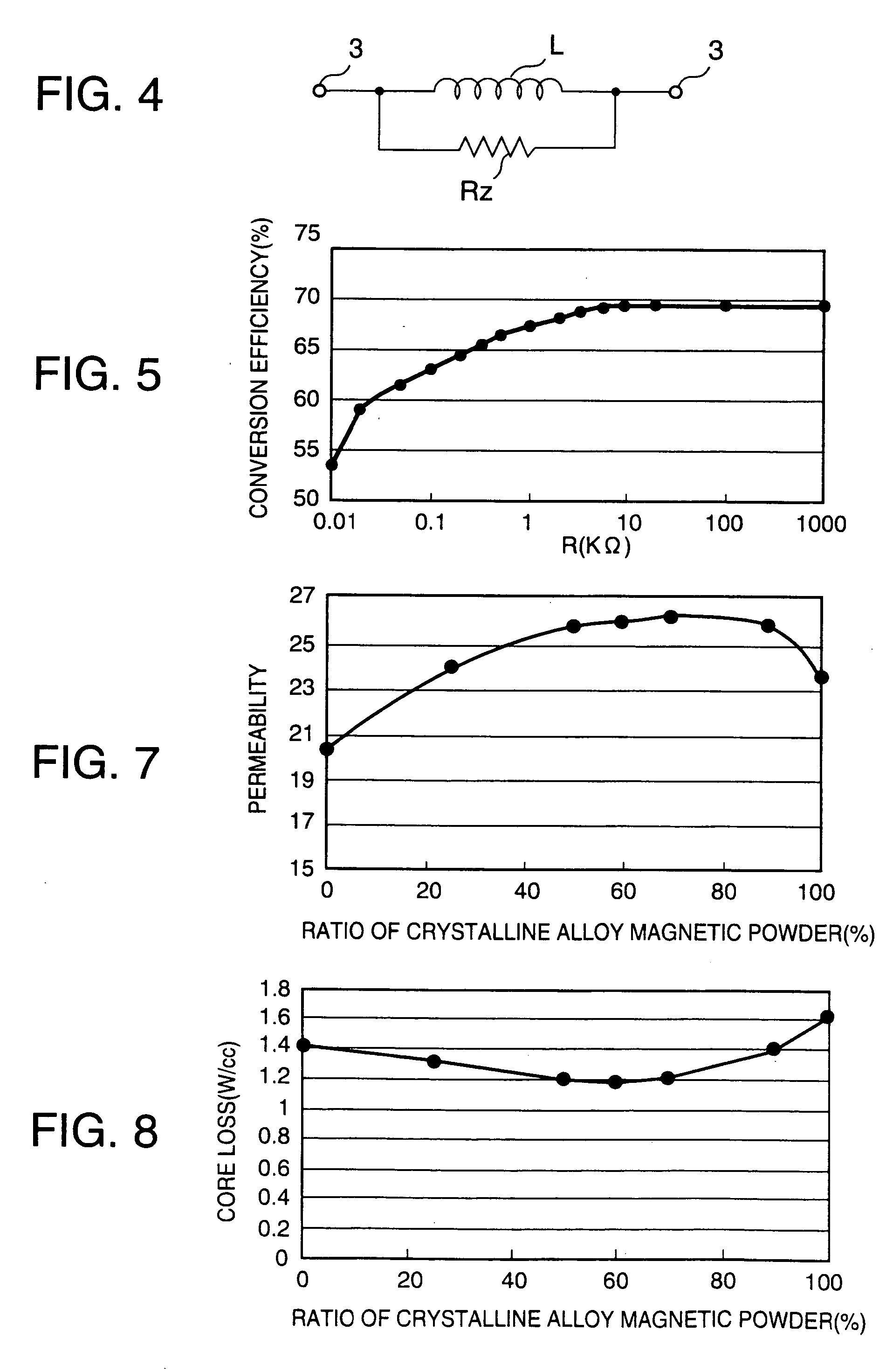
[0039] Subsequently, an embodiment of this invention will be explained. Firstly, there were prepared several types of mixed magnetic powder, comprised by mixing a ferrous crystalline alloy magnetic powder with a ferrous amorphous alloy magnetic powder at matching ratios of between 10 wt % to 90 wt %, and 90 wt % to 10 wt %, respectively, and insulating connecting agents containing mixed magnetic powder of 3 wt % were mixed into these mixed magnetic powders (100 wt %) to obtain several types of complex magnetic materials.

[0040] Si and Cr accounted for 7 wt % of the crystalline alloy magnetic powder of these complex magnetic materials, the remainder comprising iron; in the case of the amorphous alloy magnetic powders, Si and Cr accounted for 7 wt %, with the remainder comprising iron. Several wt % of a smoothing agent, such as stearic chloride, was added to and mixed with particles of the complex magnetic material containing an insulating connecting agent of epoxy resin, and the resul...


PUM

PropertyMeasurementUnit
particle diametersaaaaaaaaaa
saturation flux densityaaaaaaaaaa

Abstract

Conventional single-piece molded-type inductors are made by pressure-molding magnetic particles of ferroalloy, and have a problem that their insulation resistance drops sharply when placed in a high-temperature environment. Complex magnetic powder is obtained by mixing ferrous crystalline alloy magnetic powder with ferrous amorphous alloy magnetic powder, a connecting agent of 1 wt % to 10 wt % of the mixed magnetic powder being additionally mixed therein, producing a complex magnetic material for use in electronic components. Furthermore, a core is pressure-molded from the complex magnetic material, and a coil is buried in the core to obtain a magnetic element, such as an inductor.

Description

[0001] 1. Field of the Invention[0002] This invention relates to a magnetic material comprising ferroalloy, and a core and a magnetic element, such as an inductor, comprised by using the magnetic material.[0003] 2. Description of the Related Art[0004] Processing speeds of laptop computers and MPUs for servers have become much faster in recent years, resulting in a sharp increase in the amount of current supplied.[0005] Noticeable advancements has also been made in achieving higher switching frequencies, which are aimed at producing smaller DC-DC converters, with a consequent demand for lower inductances in the power inductors used in DC / DC converters.[0006] Conventionally, this type of power inductor is realized by using a ferrite magnetic body; however, although the ferrite magnetic body has high permeability, suitable for high inductance, it has a comparatively low saturation flux density of between 0.3 T (Tesla) and 0.4 T, and therefore tends to become magnetically saturated when...

Claims


Application Information

Patent Timeline
Patent Type & Authority Applications(United States)
IPC IPC(8): H01F1/153H01F3/08H01F17/04
CPCH01F1/15308H01F17/04H01F3/08
Inventor WATANABE, SHIGETOSHINAKAYAMA, KAZUHIROMURAKAMI, HIROMIMURAKAMI, YOSHITAKA
Owner TOKO KABUSHIKI KAISHA
Why Eureka
Try Eureka