Fuel injection valve

a technology of fuel injection valve and fuel injection pump, which is applied in the direction of fuel injecting pump, generator/motor, machine/engine, etc., can solve the problems of affecting the operation of the fuel injection pump, the sealing of the rubber sleeve, and the clamping of the ring

a technology of fuel injection valve and fuel injection pump, which is applied in the direction of fuel injecting pump, generator/motor, machine/engine, etc., can solve the problems of affecting the operation of the fuel injection pump, the sealing of the rubber sleeve, and the clamping of the ring

US20040118950A1Inactive Publication Date: 2004-06-24ROBERT BOSCH GMBH

Image

  • Fuel injection valve
  • Fuel injection valve

Examples


Embodiment Construction

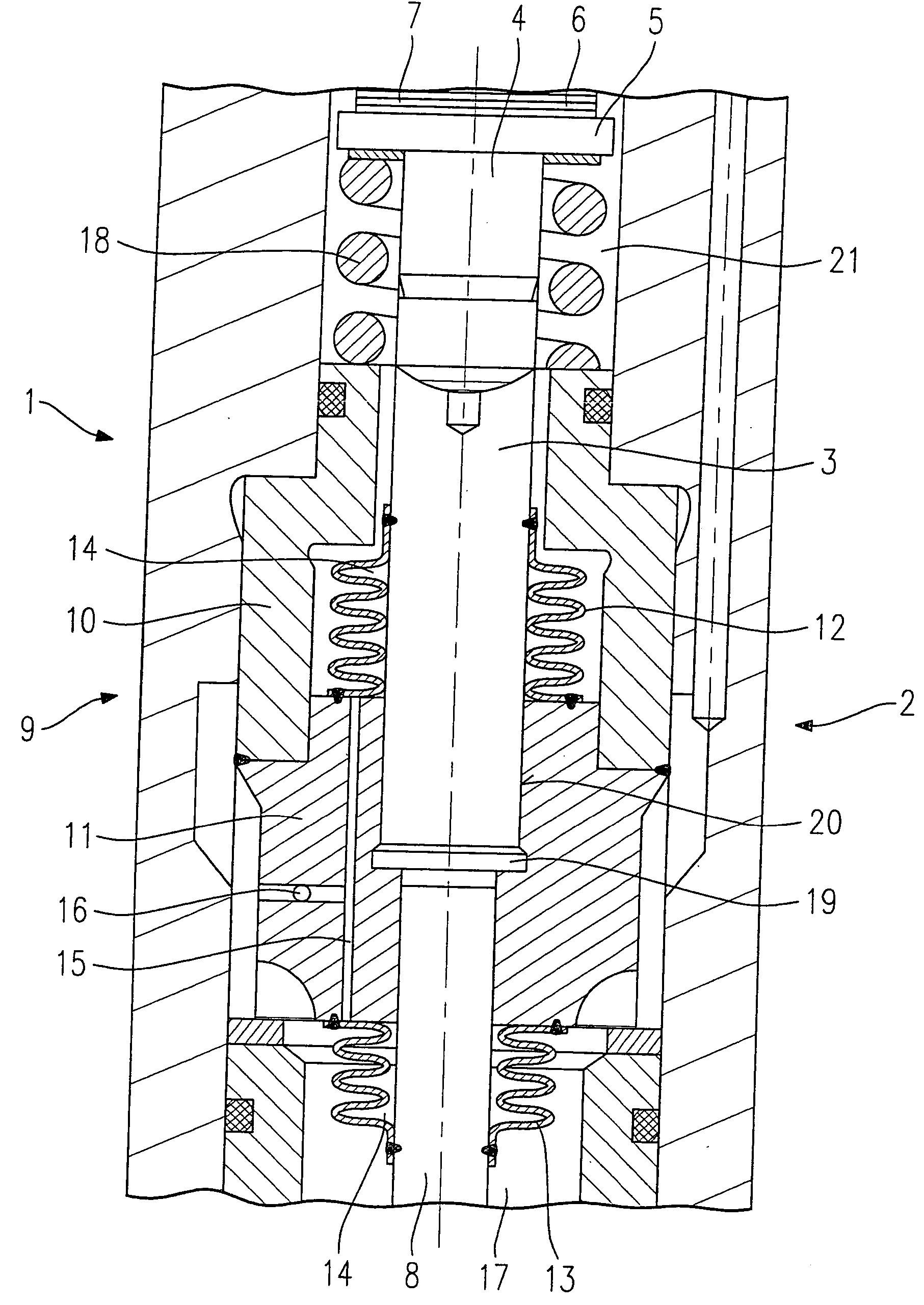
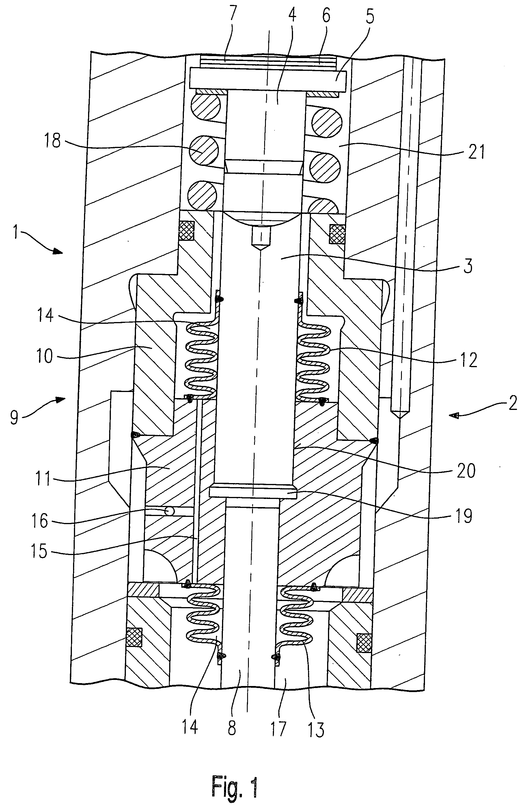
[0014] FIG. 1 shows a schematic cut-away portion of a fuel injector 1, the region of an hydraulic coupler 2 being represented. Fuel injector 1 is used, in particular, for the direct injection of fuel into a combustion chamber of a mixture-compressing internal combustion engine having externally supplied ignition.

[0015] Coupler 2 includes a master piston 3 on which an actuating member 4 is braced. On the inflow side, actuating member 4 widens to an actuator base 5 against which a piezoelectric or magnetostrictive actuator 6 abuts. Actuator 6 may be made up of a plurality of piezoelectric or magnetostrictive layers 7.

[0016] A slave piston 8 is arranged on the downstream side of master piston 3. Slave piston 8 and master piston 3 are encapsulated in a two-part coupler housing 9. A first part 10 and a second part 11 of coupler housing 9 are interconnected, for instance by welding. 3 Via a first seal 12, which is in the form of a corrugated tube and welded to master piston 3, master pist...


PUM


Abstract

A fuel injector (1) for the direct injection of fuel into the combustion chamber of an internal combustion engine includes a piezoelectric or magnetostrictive actuator (6) and an hydraulic coupler (2), the coupler (2) having a master piston (3) and a slave piston (8), which are connected to a pressure chamber (14), and the pressure chamber (14) being filled with an hydraulic fluid. The pressure chamber (14) is sealed from an actuator chamber (21) by a first seal (12) and from a valve interior chamber (17) by a second seal (13).

Description

BACKGROUND INFORMATION[0001] The present invention is directed to a fuel injector of the type set forth in the main claim.[0002] From the European Patent 0 477 400 A1, an hydraulic coupler for a piezoelectric actuator is known in which the actuator transmits a lifting force to a master piston. The master piston is in force-locking connection to a guide cylinder for a slave piston. The slave piston, the guide cylinder and the master piston sealing the guide cylinder form an hydraulic chamber. A spring, which presses the master piston and the slave piston apart, is arranged in the hydraulic chamber. Surrounding an end section of the guide cylinder and the slave piston is a rubber sleeve by which a supply chamber for a viscous hydraulic fluid is sealed from a fuel chamber. The viscosity of the hydraulic fluid is adapted to the ring gap between the slave piston and the guide cylinder.[0003] The slave piston mechanically transmits a lifting movement to a valve needle, for instance. When ...

Claims


Application Information

Patent Timeline
24 Jun 2004
Publication
US20040118950A1
IPC
F02M51/06; F02M61/08; F02M61/16; F02M63/00; H02N2/04
CPC
F02M51/0603; F02M61/08; F02M2200/707; F02M2200/16; F02M2200/703; F02M61/167
Inventors
HOHL, GUENTHER; HUEBEL, MICHAEL