Circuit and method for testing high speed data circuits

a high-speed data and circuit technology, applied in the field of circuits, can solve the problems of not being able to test thoroughly, not being able to maintain the integrity of gigahertz signals, and being practicable for fairly low frequencies

Inactive Publication Date: 2004-06-24
MENTOR GRAPHICS CORP
View PDF6 Cites 43 Cited by
  • Summary
  • Abstract
  • Description
  • Claims
  • Application Information

AI Technical Summary

Problems solved by technology

Although a PMU can deliver and measure a signal accurately, it is only suitable for DC or very low frequencies.
1149.4 offers a way to embed test capabilities in an IC, but it is only practical for fairly low frequencies, much lower than the gigahertz rate at which some ICs transmit signals.
A primary difficulty in testing gigahertz signals is maintaining signal integrity when accessing the signals.
Some circuits are simply tested for less than one second to verify that no bit errors are detected, but this is not a very thorough test.

Method used


Image

  • Circuit and method for testing high speed data circuits
  • Circuit and method for testing high speed data circuits
  • Circuit and method for testing high speed data circuits

Examples


Embodiment Construction

[0037] In the following detailed description, numerous specific details are set forth in order to provide a thorough understanding of the present invention, However, it will be understood by those skilled in the art that the present invention may be practiced without these specific details. In other instances, well known methods, procedures, components and circuits have not been described in detail so as not to obscure aspects of the present invention.

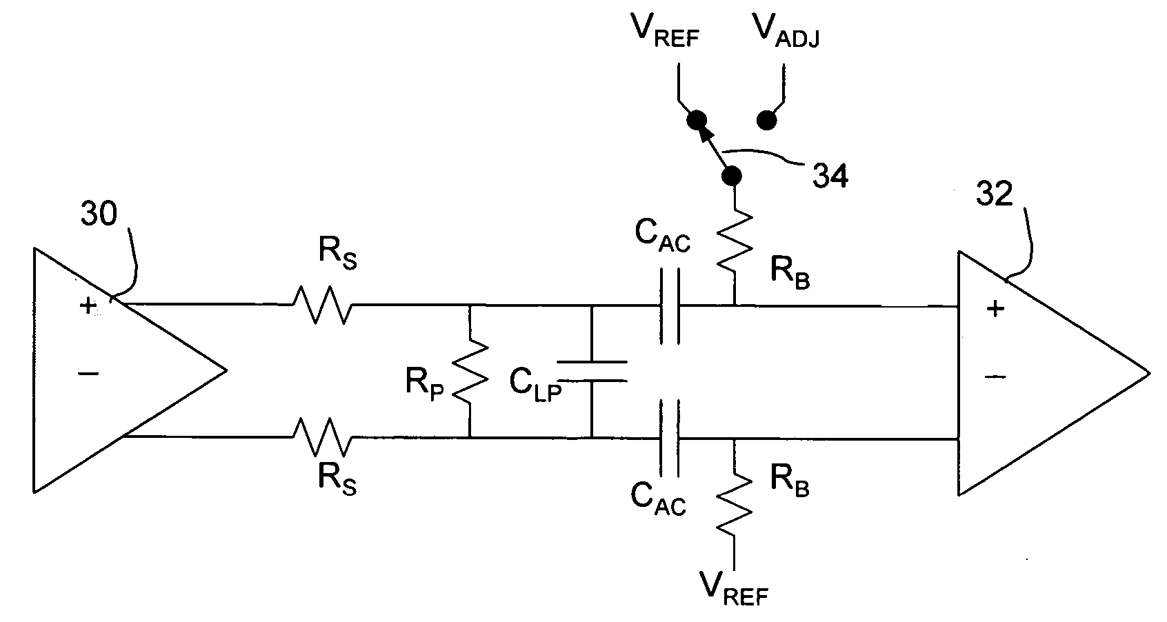
[0038] As mentioned previously, the method of the present invention is intended for testing circuits that transmit and / or receive data values via high frequency signals, using only low frequency analog test circuitry, and generally comprises coupling a transmitter of the signals to a receiver via a capacitance C.sub.AC and connecting an input of the receiver to a bias voltage, applying a source of DC current to the receiver input via an impedance, R.sub.B, which may be a resistor as shown or an inductance, transmitting one or more sequ...


PUM


Abstract

A circuit and method are described in which a DC voltage or current is connected to a high frequency, AC-coupled signal path between a transmitter and a receiver, and the bit error rate of the data transmission is tested while applying an altered bias voltage to the received signal. The bias voltage can be connected via a resistor, inductor or transistors. The transmitted signal is attenuated resistively, and a load capacitance is applied whose value causes digital transition times to exceed one unit interval. An intended application is testing of an integrated circuit, serializer / deserializer (serdes) operating above 1 GHz.

Description

[0001] This application claims the benefit of U.S. Provisional Patent Application Serial No. 60 / 433,989 filed Dec. 18, 2002.[0002] 1. Field of the Invention[0003] The present invention generally relates to the testing of circuits, and, more specifically, to testing the data transmission performance of circuits that transmit and / or receive high speed, serial data.[0004] 2. Description of Related Art[0005] As the data rate of IC pins increases each year, well beyond a few gigahertz, it becomes necessary to consider embedding test capabilities in an integrated circuit (IC) so that a tester will not need to operate accurately at the data rate being tested.[0006] In automatic test equipment (ATE), it is common to include a parametric measurement unit (PMU) to measure the drive of an IC's output pin, or to accurately deliver a DC voltage. The output drive of a pin is tested by applying a known current to the pin and measuring the resultant voltage at the pin, or by applying a known voltag...

Claims


Application Information

Patent Timeline
Patent Type & Authority Applications(United States)
IPC IPC(8): G01R31/28G01R31/317G01R31/3185
CPCG01R31/2834G01R31/2884G01R31/3171G01R31/318594G01R31/318577G01R31/31858G01R31/31725
Inventor SUNTER, STEPHEN K.ROY, AUBIN P. J.
Owner MENTOR GRAPHICS CORP
Why Eureka
Try Eureka