Apparatus and method for enhancing low-frequency operation of mobile communication antennas

a mobile communication antenna and low-frequency operation technology, applied in the direction of antennas, antenna supports/mountings, transmission, etc., can solve the problems of reducing the efficiency of small antennas, and requiring higher power supply, so as to enhance the operation efficiency and bandwidth of antennas, and enhance the operation efficiency of such antennas

Inactive Publication Date: 2004-07-01
IN4TEL
View PDF28 Cites 69 Cited by
  • Summary
  • Abstract
  • Description
  • Claims
  • Application Information

AI Technical Summary

Benefits of technology

0009] An object of the present invention is to provide mobile communication apparatus including small, compact antennas, wherein the operating efficiency

Problems solved by technology

For advanced mobile communication devices, e.g., cellular telephone handsets, such dimensions are impractical since the overall handset dimensions are smaller than half a wavelength of the appropriate frequency.
Using small antennas therefore reduces their efficiency, and accordingly requires higher power to be supplied.
The level of power radiated into the human head is particularly significant, and serious limitations and specifications are prescribed in order to reduce this possible hazard to the users.
However, the use of such antennas is also inconvenient as the antennas are often "caught up" inside the pocket.
They also detract from the aesthetic appearance of the mobile communication device.
Moreover, their radiation pattern is quasi-omni so as to provide little protection of the user's head/body against excessive radiation.
Internal antennas supplied by several companies are relatively inefficient as compared to external antennas.
Furthermore, these known internal antennas generally do not decrease the radiation into the user's head/body, and in many cases even increase such radiation.
The antenna gain is also generally poor (especially while used adjacent to the head/body), and the SAR (Specific Absorption Ratio) results are generally h

Method used


Image

  • Apparatus and method for enhancing low-frequency operation of mobile communication antennas
  • Apparatus and method for enhancing low-frequency operation of mobile communication antennas
  • Apparatus and method for enhancing low-frequency operation of mobile communication antennas

Examples


Embodiment Construction

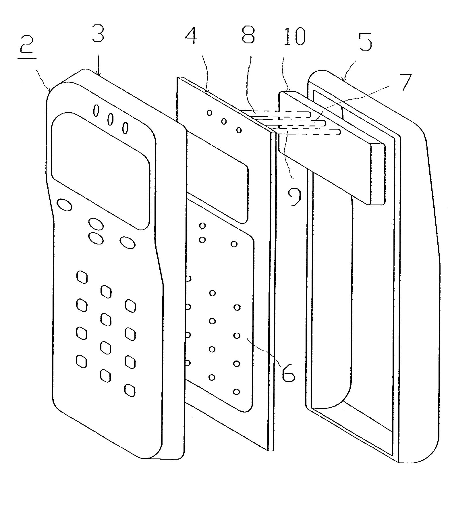
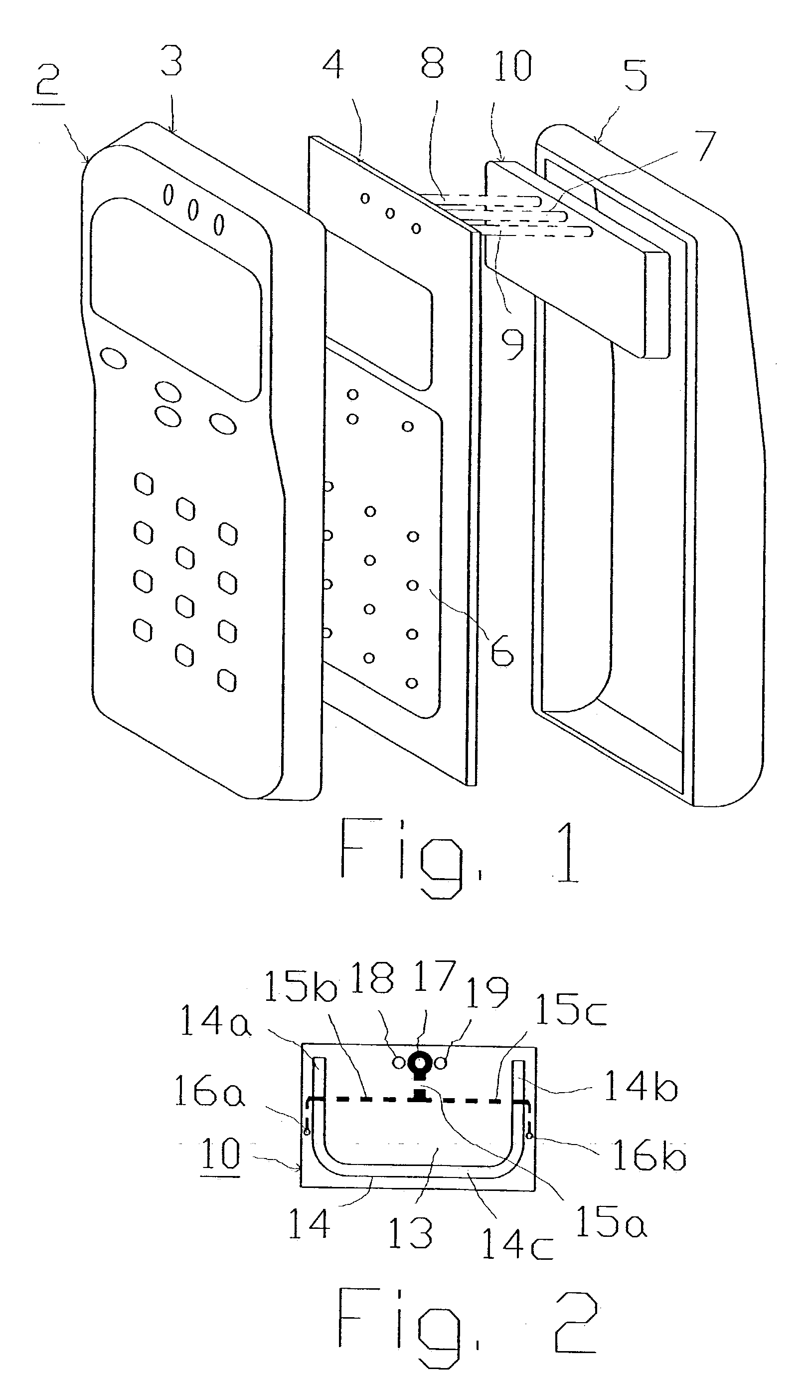
[0030] With reference first to FIG. 1, there is illustrated one form of mobile communication apparatus constructed in accordance with the present invention, including a housing, generally designated 2, constituted of a front cover 3 and a back cover 5. Within housing 2 is a printed wired board (PWB) 4, sometimes referred to as a printed circuit board (PCB), which includes all or a part of the communication circuitry, generally designated 6, of the apparatus. PWB 4 is formed with a signal terminal indicated at 7, and with an electrically-conductive ground connected to ground terminals 8, 9 for the communication circuitry. The ground may be a continuous conductive layer serving as a ground plane, or may be one or more conductive strips serving as a ground for individual components of the communication circuitry.

[0031] In the apparatus illustrated in FIG. 1, terminals 7-9 are on the underlying surface of PWB 4 and face an internal antenna, generally designated 10, covering a portion of...


PUM


Abstract

The operation of a mobile communication apparatus is enhanced particularly in the lower frequency portion of its bandwidth by connecting an electrically-conductive reflector to the electrically-conductive ground of the printed wired board (PWB) containing the communication circuitry such that the reflector effectively enlarges the ground of the PWB to load the antenna in the lower portion of its radio frequency band. The reflector may include stub reflectors integrally formed on the PWB, or connected thereto, preferably at the end of the PWB opposite to that connected to the antenna. The antenna may be an internal antenna or an external antenna.

Description

FIELD AND BACKGROUND OF THE INVENTION[0001] The present invention relates to apparatus, and also to a method, for enhancing the operation of mobile communication antennas particularly in the low-frequency portion of the bandwidth or bandwidths for which the apparatus was designed. The invention is particularly useful in mobile communication apparatus (such as mobile telephone handsets) having built-in internal antennas or external antennas, and is therefore described below particularly for such applications.[0002] Mobile communication equipment, including their antennas, are becoming smaller in size as the technology is developed. For an antenna to operate properly, it should usually be about half a wavelength in size, except for monopole-like antennas (which normally operate above a ground plane) where a quarter wavelength is required. For advanced mobile communication devices, e.g., cellular telephone handsets, such dimensions are impractical since the overall handset dimensions a...

Claims


Application Information

Patent Timeline
IPC IPC(8): H01Q19/10H01Q1/24H01Q1/48H01Q9/04H01Q9/40H01Q13/10H04B1/38H04M1/02
CPCH01Q1/242H01Q1/243H01Q1/48H01Q13/106H01Q9/0421H01Q9/0442H01Q9/0407H01Q1/24
Inventor MAOZ, JOSEPHKADICHEVITZ, MICHAEL
Owner IN4TEL
Why Eureka
Try Eureka