Luminescene measuring device with prefilter effect suppression

a technology of prefilter and measurement device, which is applied in the direction of material analysis, instruments,spectrum investigation, etc., can solve the problems of increasing the dispersion of analyses, increasing the cost of various measurement types, and inconvenient in-line analysis of luminescence techniques

Inactive Publication Date: 2004-07-08
COMMISSARIAT A LENERGIE ATOMIQUE ET AUX ENERGIES ALTERNATIVES
View PDF4 Cites 6 Cited by
  • Summary
  • Abstract
  • Description
  • Claims
  • Application Information

AI Technical Summary

Problems solved by technology

Luminescence techniques are then unsuitable for in-line analysis.
These various measurement types are expensive both in terms of time and equipment.
They ar

Method used


Image

  • Luminescene measuring device with prefilter effect suppression
  • Luminescene measuring device with prefilter effect suppression
  • Luminescene measuring device with prefilter effect suppression

Examples


Embodiment Construction

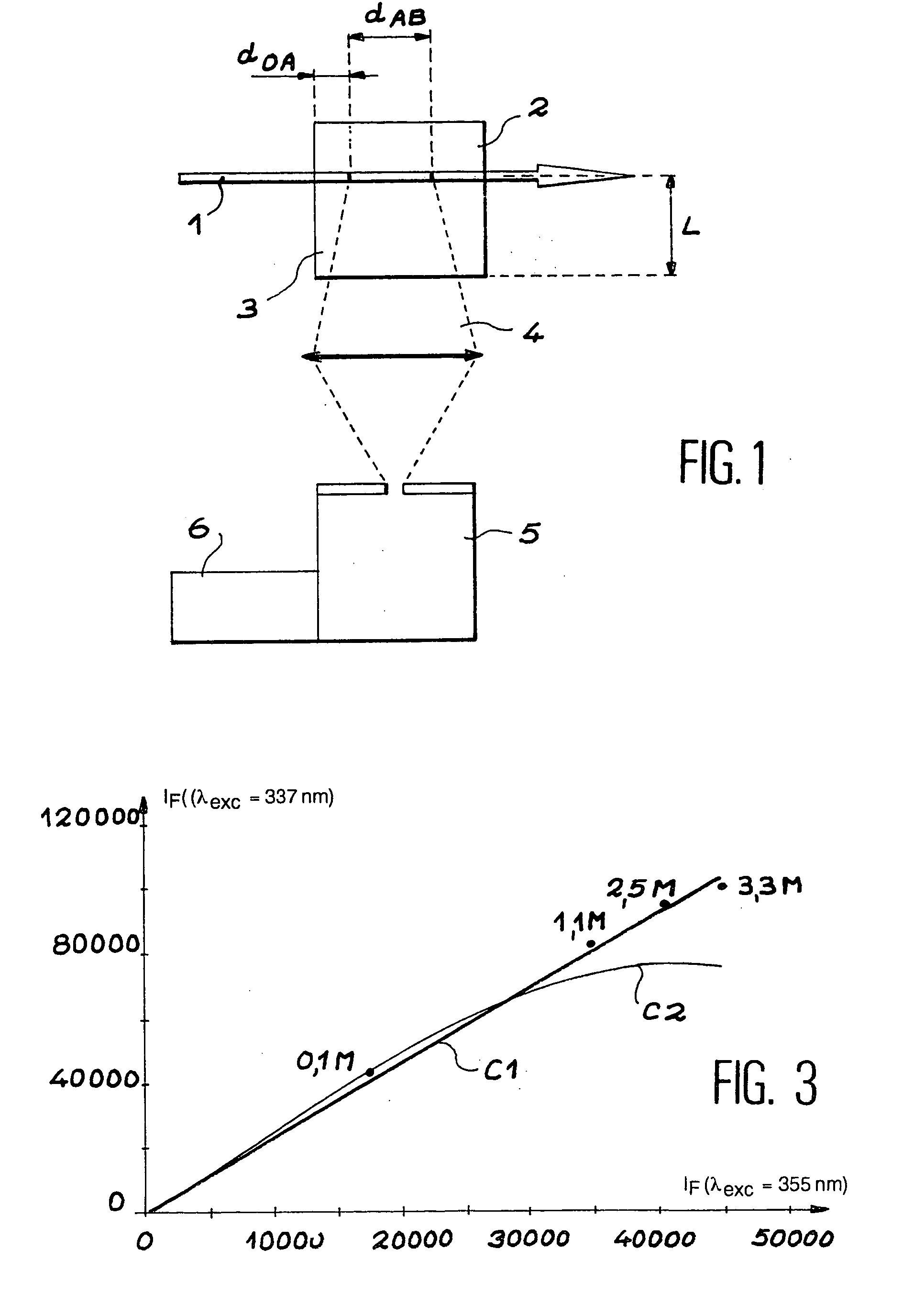
[0043] FIG. 1 has already been described above, therefore there is no point in describing it again.

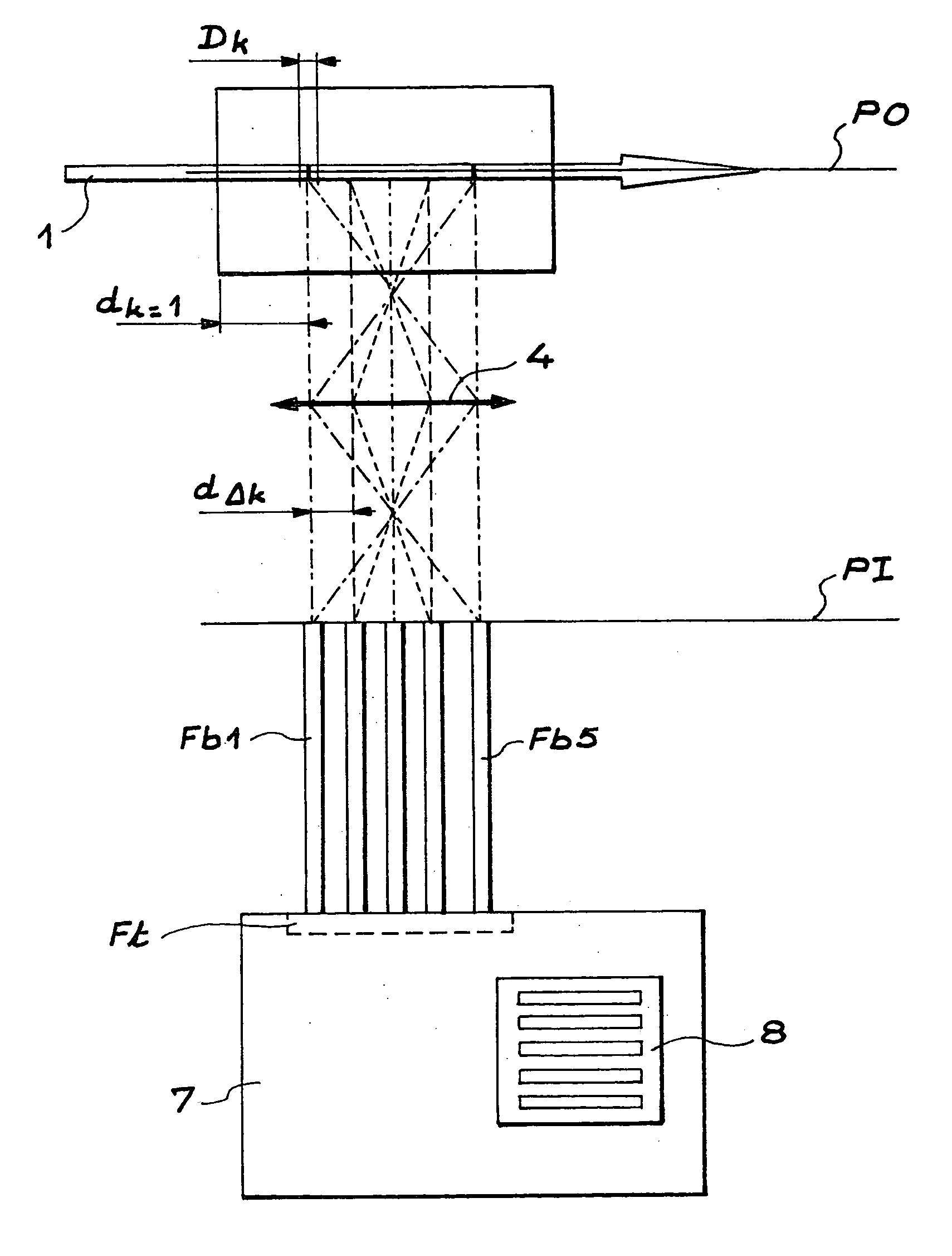
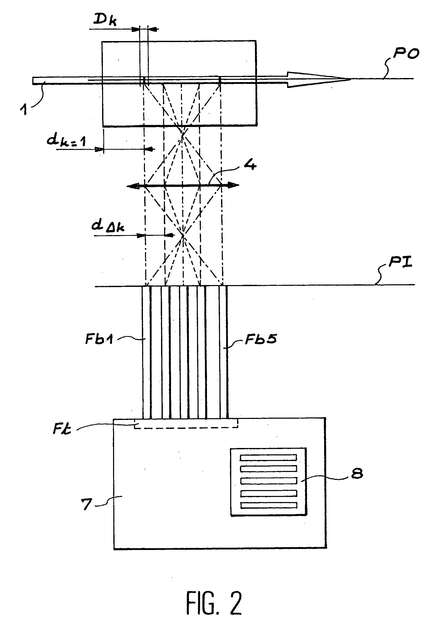
[0044] FIG. 2 shows a luminescence measurement device according to the invention. The measurement device comprises an optical lens 4 preferably installed in double focus (2f), a set of n optical fibres Fbi (5 optical fibres are shown in FIG. 2 as a non-limitative example) and a plane field spectrometer 7.

[0045] An assembly type other than the double focus optical assembly may also be used, but there would then be the disadvantage that the system could not be easily calibrated.

[0046] The excitation radiation 1 passes through the measurement cell 2. The luminescence radiation emitted in the direction approximately perpendicular to the beam axis is collected on the optical lens 4. The chemical species is probed along a trajectory located in the object plane PO of the lens. The number of n of optical fibres is equal to at least 2. Each optical fibre collects a fraction of the luminescence ...


PUM


Abstract

The invention relates to a device for measuring the intensity of a luminescence radiation emitted by at least one chemical species probed, along a trajectory by an excitation radiation. The device comprises n measurement channels, where n is an integer greater than or equal to 2, each measurement channel being used to measure a fraction of the intensity of the luminescence radiation emitted along the trajectory. The invention is also applicable to analytical chemistry to make speciation measurements.

Description

TECHNICAL DOMAIN AND PRIOR ART[0001] The invention relates to a luminescence measurement device.[0002] More particularly, the invention relates to a luminescence measurement device with elimination of the pre-filter effect.[0003] A luminescence (fluorescence or phosphorescence) measurement device comprises means of exciting a chemical species by electromagnetic radiation for which the wavelength is tuned to one of the electrical transitions of the chemical species, optical means for collecting and diffracting the emitted luminescence radiation and means of measuring the intensity of the luminescence spectrum.[0004] A principle diagram for a luminescence measurement device is shown in FIG. 1. A measurement cell 2 contains a chemical species 3. An excitation radiation 1 passes through the measurement cell 2. The luminescence radiation emitted in direction approximately perpendicular to the axis of the excitation beam 1 is collected on an optical lens 4 and is focused on a spectrometer...

Claims


Application Information

Patent Timeline
IPC IPC(8): G01N21/64
CPCG01N21/6456G01N2021/6491G01N2021/6484
Inventor COUSTON, LAURENTDELAGE, JACQUES
Owner COMMISSARIAT A LENERGIE ATOMIQUE ET AUX ENERGIES ALTERNATIVES
Why Eureka
Try Eureka