Photoelectrochemical Cell

a photoelectrochemical and cell technology, applied in the field of photoelectrochemical cells, can solve the problems high cost, and obtaining power to be consumed, and achieves the effects of reducing the concentration of carbon dioxide, and reducing the current efficiency of supplied power

Inactive Publication Date: 2008-11-20
NISSAN MOTOR CO LTD
View PDF3 Cites 80 Cited by
  • Summary
  • Abstract
  • Description
  • Claims
  • Application Information

AI Technical Summary

Benefits of technology

[0017]However, such a technique for separation and concentration of carbon dioxide using redox mediator as described is like to techniques before then, as still needing separation energy. Further, as the concentration of carbon dioxide in electrolyte (ionic liquid) is low, the redox mediator non-bonded to carbon dioxide has a higher concentration than the redox mediator bonded to carbon dioxide, whereby a redox cycle routing the formula (3), which is non-contributable to the separation and concentration of carbon dioxide, appears in a greater number of rounds than a redox cycle routing the formula (2) serving for the separation and concentration of carbon dioxide. Therefore, such a fraction of current that does not contribute to separation and concentration of carbon dioxide is consumed as an IR drop encompassing the electrochemical cell and power supply system, with a resultant decrease in current efficiency of supplied power, as a problem. In particular, the current efficiency goes down, as the carbon dioxide concentration is decreased in gases containing carbon dioxide to be separated and concentrated.

Problems solved by technology

However, such a technique for separation and concentration of carbon dioxide using redox mediator as described is like to techniques before then, as still needing separation energy.
Therefore, such a fraction of current that does not contribute to separation and concentration of carbon dioxide is consumed as an IR drop encompassing the electrochemical cell and power supply system, with a resultant decrease in current efficiency of supplied power, as a problem.
Like this, for electrochemical separation and concentration of carbon dioxide, if the electric power available from an external power supply is generated by use of a fossil fuel as in a thermal power plant, it so follows that the procurement of necessary power for separation and concentration of carbon dioxide is bound to an emission of carbon dioxide, which is undesirable, while it is desirable to use power generated at a renewable energy source.
However, even in use of power generated by a solar cell for example, the power to be consumed is obtained at a certain generation cost, in addition to that stored power is to be consumed also for vain redox cycle else than separation and concentration of carbon dioxide, costing high, as a problem.

Method used


Image

  • Photoelectrochemical Cell
  • Photoelectrochemical Cell
  • Photoelectrochemical Cell

Examples


first embodiment

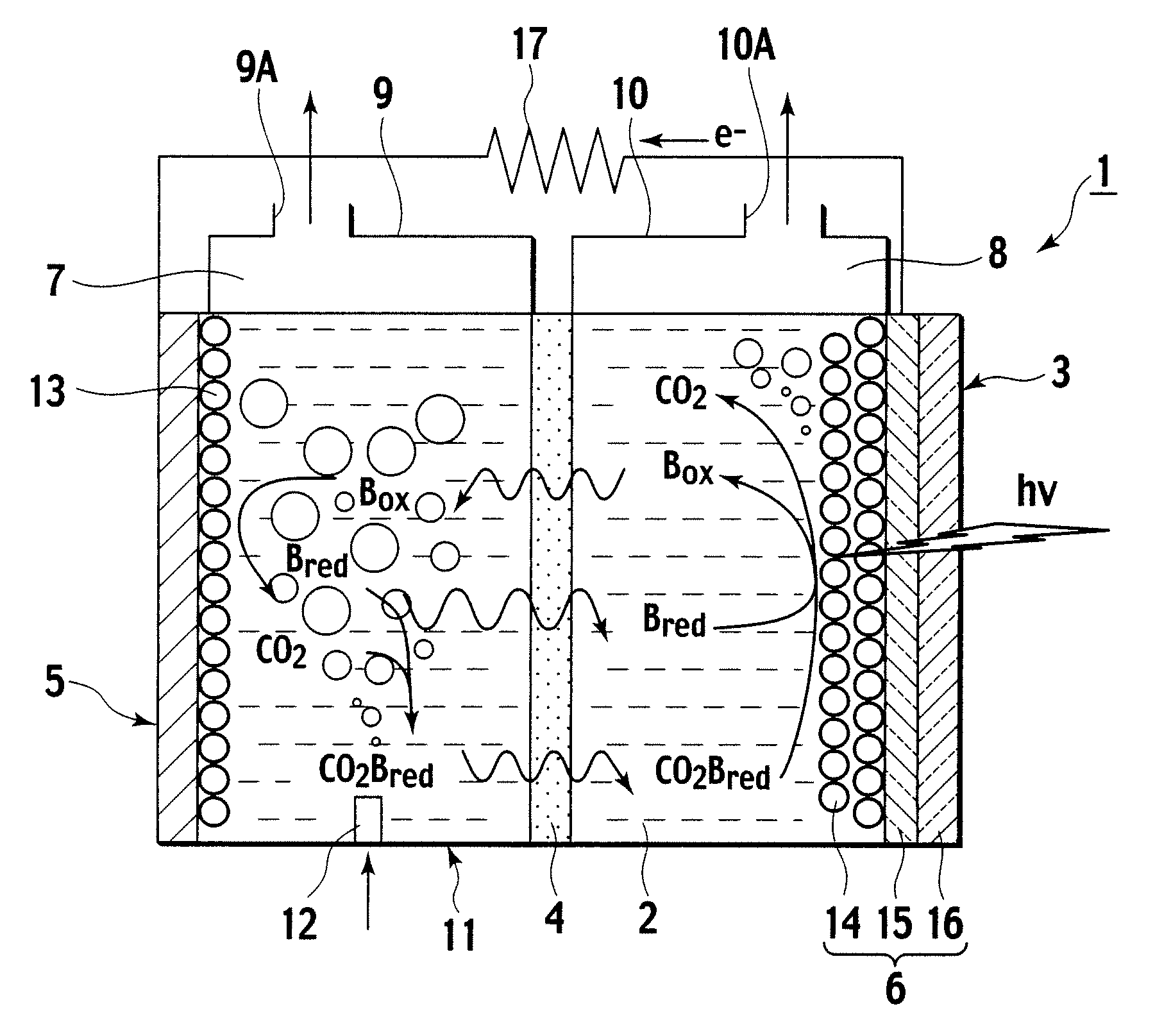
[0039]Description is now made of a photoelectrochemical cell according to a first embodiment of the invention, with reference made to FIG. 1. As shown in FIG. 1, the photoelectrochemical cell 1 according to this embodiment includes an electrolyte container 3 containing an ionic liquid 2 as an electrolyte, and a partitioning membrane 4 dividing an interior of the electrolyte container 3 into two to be a left and a right.

[0040]The electrolyte container 3 has opposing sidewalls with the partitioning membrane 4 in between, of which one is made as a carbon electrode 5, and the other as an optical electrode 6.

[0041]Further, the electrolyte container 3 is divided into a CO2 capturing chamber 7 and a CO2 releasing chamber 8, with the partitioning membrane 4 in between. Then, over the CO2 capturing chamber 7, an upper wall portion 9 is formed, and an emission port 9A is formed in the upper wall portion 9. Over the CO2 releasing chamber 8, an upper wall portion 10 is formed, and a CO2 take-ou...

second embodiment

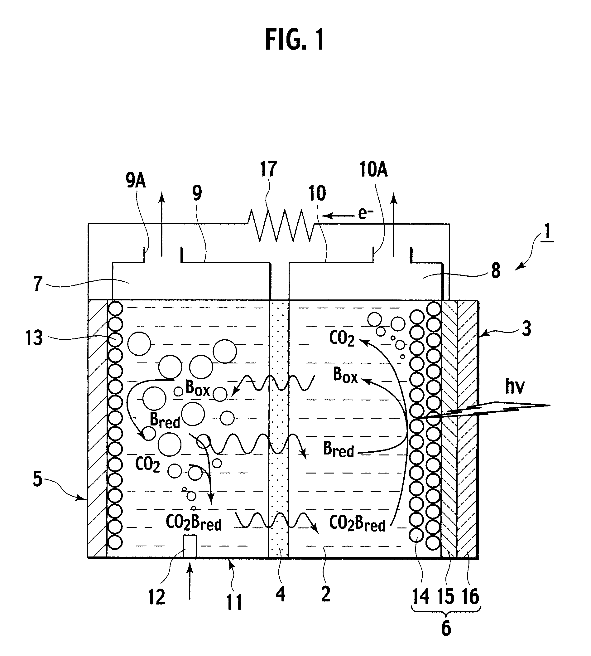
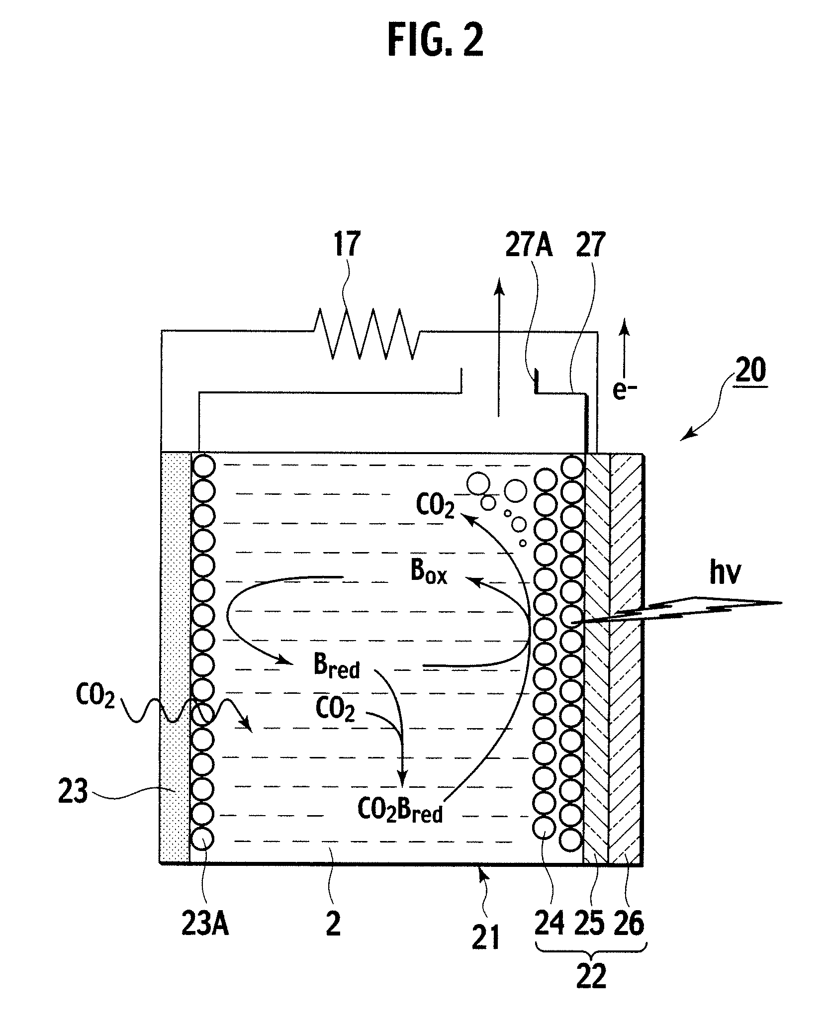
[0064]Description is now made of a photoelectrochemical cell according to a second embodiment of the invention, with reference made to FIG. 2 to FIG. 4.

[0065]As shown in FIG. 2, the photoelectrochemical cell 20 according to this embodiment includes an electrolyte container 21, an optical electrode 22, and a porous carbon electrode 23. The optical electrode 22 and the porous carbon electrode 23 concurrently serve as sidewalls of the electrolyte container 21 at mutually opposing positions. This embodiment is not configured with a partitioning membrane as in the photoelectrochemical cell 1 according to the first embodiment described.

[0066]The porous carbon electrode 23, made of carbon of a porous structure, is set to be impermeant to an ionic liquid 2, but permeable simply for gaseous bodies. This embodiment is configured to take in carbon dioxide of exhaust gases into ionic liquid 2, not by a bubbling of exhaust gases introduced into the ionic liquid 2, but by exposing an outside of p...

third embodiment

[0074]Description is now made of a photoelectrochemical cell according to a third embodiment of the invention, with reference made to FIG. 5 and FIG. 6. According to this embodiment, the photoelectrochemical cell 30 is configured to be the photoelectrochemical cell 20 according to the second embodiment, as this is modified to have a porous carbon electrode formed cylindrical, and adapted to pass exhaust gases through a cylindrical hollow of the cylindrical porous carbon electrode.

[0075]As shown in FIG. 5 and FIG. 6, the photoelectrochemical cell 30 according to this embodiment includes an electrolyte container 31, an optical electrode 32 constituting part of a sidewall of the electrolyte container 31, and a porous carbon electrode 33 formed cylindrical so as to vertically extend through and within the electrolyte container 31. The porous carbon electrode 33 is disposed in a position set off from the optical electrode 32. This embodiment is not configured with a partitioning membrane...


PUM

PropertyMeasurementUnit
bonding forcesaaaaaaaaaa
bonding forceaaaaaaaaaa
transparentaaaaaaaaaa

Abstract

A photoelectrochemical cell (1) includes an electrolyte container (3) containing an ionic liquid (2), and a partitioning membrane (4) dividing an interior of the electrolyte container (3) into two being a CO2 capturing chamber (7) and a CO2 releasing chamber (8), having side walls opposing each other, with the partitioning membrane (4) in between, either as a carbon electrode (5) and the other as a photoelectrode (6). A redox mediator (B) has different bonding forces to carbon dioxide, as it appears as an oxidant Box and a reductant Bred, of which that one which has a greater bonding force serves as an intermediary chemical species carrying carbon dioxide to one of the paired electrodes (5, 6). Over the CO2 releasing chamber (10), an upper wall portion (10) is formed, which has a CO2 take-out port (10A) formed therein, for making use of oxidation and reduction of the redox mediator to achieve separation and concentration of carbon dioxide, converting photo energy of sunlight into electric power.

Description

TECHNICAL FIELD[0001]The present invention relates to a photoelectrochemical cell, and in particular, to a photoelectrochemical cell with a function for separation and concentration of carbon dioxide.BACKGROUND ART[0002]Recent years have observed researches for fixation and isolation of carbon dioxide being under intense study, as well as researches for use of carbon dioxide as a chemical raw material. In any case of research, carbon dioxide had better be collected by separation and concentration from the atmosphere, or from waste or exhaust gases discharged from stationary emission sources typified by a thermal power plant or the like.[0003]For separation and concentration of carbon dioxide, old techniques of membrane separation, adsorption separation, and absorption separation have been based on to forward research and development.[0004]The membrane separation method features a simple facility and operation, a clean process, and a small environmental load. The membrane separation ...

Claims


Application Information

Patent Timeline
Patent Type & Authority Applications(United States)
IPC IPC(8): H01M14/00H01L31/04B01D53/32B01D53/62B01D53/86C25B1/00
CPCB01D53/326B01D53/62B01D53/864B01D2255/802B01D2257/504Y02E10/542H01G9/2013H01G9/2018H01M14/005Y02C10/04C25B1/003C25B1/55Y02P20/133Y02P20/151Y02C20/40
Inventor IWASAKI, YASUKAZU
Owner NISSAN MOTOR CO LTD
Why Eureka
Try Eureka