Techniques for designing and manufacturing precision-folded, high strength, fatigue-resistant structures and sheet therefor

a technology of fatigue-resistant structures and folding sheets, applied in the direction of synthetic resin layered products, textiles and paper, building components, etc., can solve the problems of cumulative tolerance errors, difficult control of bend location, and insignificant cumulative tolerance errors in bending, so as to improve the bend location and improve the bend strength

Inactive Publication Date: 2004-07-15
IND ORIGAMI INC CA US
View PDF7 Cites 93 Cited by
  • Summary
  • Abstract
  • Description
  • Claims
  • Application Information

AI Technical Summary

Benefits of technology

[0053] In a broad aspect the present invention, bending strap-defining structures, which are preferably slits but may be grooves, are used to configure bending straps in the sheet of material that cause the bent sheet to have improved precision in the bend location and substantially improved bend strength.
[0054] Briefly, in a preferred embodiment a sheet of material is formed with a plurality of slits that are positioned relative to a proposed bend line and configured to allow bending of the sheet of material precisely along the bend line as a result of edge-to-face engagement of material on opposite sides of the slits during bending for increased bend strength and dimensional accuracy.
[0055] Most preferably the longitudinally adjacent slits are equally transversely spaced on opposite sides of the bend line to define bending straps that extend obliquely across the bend line. The slits are preferably arcuate with convex side facing or closest to the bend line so that the width dimension of the straps increases in both directions from a midpoint, or a constant width region, of the straps. The slits also preferably include crack propagation resisting end portions to further reduce the likelihood of stress failures.
[0057] In one embodiment, the slitting step is accomplished by forming two elongated slits longitudinally shifted along the bend line, with each slit having a slit end portion which diverges away from the bend line to provide a pair of adjacent slit portions on opposite sides of the bend line which define an oblique bending strap extending across the bend line with increasing width in both directions from the bend line. The slit kerf and jog distance between opposing rows of arcuate slits are dimensioned and positioned to produce interengagement of an edge of the sheet of material on one side of the slits with a face of the sheet of material on the opposite side of the slits during bending. Most preferably the slits are arcuate and produce continuous and progressive engagement of an edge with an opposing face, with the result that the edge is resiliently clamped and held against the opposing face over a substantial portion of the length of the slit during bending for control of the bending precision and enhancement of the strength of the bent sheet.

Problems solved by technology

A commonly encountered problem in connection with bending sheet material is that the locations of the bends are difficult to control because of bending tolerance variations and the accumulation of tolerance errors.
The second bend, however, often is positioned based upon the first bend, and accordingly, the tolerance errors can accumulate.
Since there can be three or more bends which are involved to create the chassis or enclosure for the electronic components, the effect of cumulative tolerance errors in bending can be significant.
Nevertheless, even a grooving-based or slitting-based bending of sheet material has its problems.
Moreover, the grooves or slits do not necessarily produce bending of webs 27 directly along bend line 25, and the grooving process is slow and inconsistent, particularly when milling or point cutting V-shaped grooves.
Grooving, therefore, is not in widespread commercial use.
Failure of the structure will occur at lower force levels than if a non-slitting or non-grooving bending process was used.
The architects of the New York Museum of Modern Art sculpture recognized that the resulting bend is not structurally very strong, and they have incorporated partially hidden beams welded into the sculpture in the inner vertices of each of the stitched bends.
This tends to compromise the strength of the bend and leaves a non-load bearing bend.
Another problem inherent in the slitting scheme of FIGS. 2-2B and the Gitlin, et al.
This limits the flexibility in designing the bends for structural loading of the straps.
There is no attempt, therefore, to reduce stress risers and micro-crack propagation from occurring at the ends of the slits, and aligned slit ends can crack under loading.
The sheet slitting configuration of FIGS. 2-2B, therefore, can be readily employed for decorative bends, but it is not optimally suited for bends which must provide significant structural support and fatigue resistance.
Again, the bent sheet components by linear perforation were not designed to bear significant unsupported loads along the bends.
In most of these prior art bending systems, however, the bend forming technique greatly weakens the resulting structure, or precision bends are not capable of being formed, or bending occurs by crushing the material on one side of the bend.
Moreover, when slitting is used in these prior art systems, in addition to structural weakening and the promotion of future points of structural failure, the slitting can make the process of sealing a bent structure expensive and difficult.
These prior art methods, therefore, are less suitable for fabricating structures that are capable of containing a fluid or flowable material.
The problems of precision bending and retention of strength are much more substantial when bending metal sheets, and particularly sheets of substantial thickness.
Such bending of thick metal sheets, of course, poses greater problems.
In the case of welding, for example, a problem arises in the accurate cutting and jigging of the individual pieces; the labor and machinery required to manipulate a large number of parts, as well as the quality control and certification of multiple parts.
Additionally, welding has the inherent problem of dimensional shape warping caused by the heat-affected zone of the weld.
Traditional welding of metals with significant material thickness is usually achieved by using parts having beveled edges often made by grinding or single point tools, which add significantly to the fabrication time and cost.
Moreover, the fatigue failure of heat-affected metals is unpredictable for joints whose load-bearing geometries rely entirely on welded, brazed or soldered materials.
The attendant disadvantage of such over design is, of course, excessive weight.
With respect to adhesively bonding sheet and non-sheet material along the edges and faces of discrete components, a problem arises from the handling and accurate positioning the several parts and holding or clamping them in place until the bonding method is complete.
The problems associated with subtractive Rapid Prototyping methods are that they are wasteful of materials in that a block of material capable of containing the entire part is used and then a relatively expensive high-speed machining center is required to accurately mill and cut the part by removal of the unwanted material.
Problems also exist with prior art additive Rapid Prototyping techniques.
The additive Rapid Prototyping processes are slow, very limited in the scale of the part envelope and usually do not make use of structurally robust materials.
Generally in the prior art, therefore, sheet slitting or grooving to enable sheet bending has produced bends, which lack the precision and strength necessary for commercial structural applications.
Thus, such prior art sheet bending techniques have been largely relegated to light gauge metal bending or decorative applications, such as sculpture.

Method used


Image

  • Techniques for designing and manufacturing precision-folded, high strength, fatigue-resistant structures and sheet therefor
  • Techniques for designing and manufacturing precision-folded, high strength, fatigue-resistant structures and sheet therefor
  • Techniques for designing and manufacturing precision-folded, high strength, fatigue-resistant structures and sheet therefor

Examples


second embodiment

[0126] It has been found that the embodiment of FIGS. 3-5C'" is best suited for use with relatively ductile sheet materials. As the material becomes harder and less ductile, a second embodiment is preferred.

[0127] In the embodiment of the present invention shown in FIGS. 6-8B a slitting configuration is employed which tucks or clamps the sheet material into interengaged relation on both sides of the slits, and also reduces bending strap plastic deformation and the residual stress in the straps. Moreover, this embodiment also allows the strap width to be varied independently of the jog distance between slits and to have the strap width increase in both directions from the bend line for less stress concentration in the connected portions of the sheet of material on opposite sides of the bend line.

[0128] A bending strap which is oblique to the bend line is employed, which allows the strap length to be increased, as compared to the shorter bending straps of FIGS. 3-5C'". Plastic deforma...

first embodiment

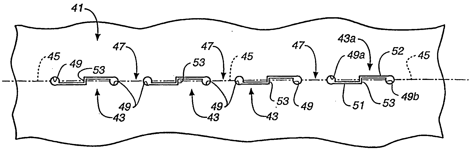
[0134] As was the case for the first embodiment, slit kerfs 243 preferably have a width dimension, and the transverse jog distance across the bend line between slits is dimensioned, to produce interengagement of sheet material on opposite sides of the slits during bending. Thus, slits 243 can be made with a knife and have essentially a zero kerf, or they can have a greater kerf which still produces interengagement, depending upon the thickness of the sheet being bent. Most preferably the kerf width is not greater than about 0.3 times the material thickness, and the jog distance is not greater than about 1.0 times the material thickness.

[0135] As was the case for the embodiment of FIGS. 3-5C . . . , a lip portion 253 extends across bend line 245 to slit 243. Lip 253 slides or rides up a face 255 of a tongue 260 on the other side of slit 243 if the kerf width and jog distance, relative to the thickness of the material, are not so large as to prevent contact between the two sides of th...


PUM

PropertyMeasurementUnit
anglesaaaaaaaaaa
anglesaaaaaaaaaa
stressaaaaaaaaaa

Abstract

A process for designing and manufacturing precision-folded, high strength, fatigue-resistant structures and a sheet therefore. The techniques include methods for precision bending of a sheet of material (41, 241, 341, 441, 541) along a bend line (45, 245, 345, 445,543) and a sheet of material formed with bending strap-defining structures, such as slits or grooves (43, 243, 343, 443, 542), are disclosed. Methods include steps of designing and then separately forming longitudinally extending slits or grooves (43, 243, 343, 443, 542) through the sheet of material in axially spaced relation to produce precise bending of the sheet (41, 241, 341, 441,541) when bent along the bend line (45, 245, 345, 445, 543). The bending straps have a configuration and orientation which increases their strength and fatigue resistance, and most preferably slits or arcs are used which causes edges (257, 457) to be engaged and supported on faces (255, 455) of the sheet material on opposite sides of the slits or arcs. The edge-to-face contact produces bending along a virtual fulcrum position in superimposed relation to the bend line (45, 245, 345, 445, 543). Several slit embodiments (43, 243, 343, 443, 542) suitable for producing edge-to-face engagement support and precise bending are disclosed, as is the use of the slit sheets to produce various three-dimensional structures and to enhance various design and fabrication techniques.

Description

[0001] This application is a Continuation-in-Part Application based upon a co-pending patent application Ser. No. 10 / 256,870, filed Sep. 26, 2002, and entitled METHOD FOR PRECISION BENDING OF SHEET OF MATERIALS, SLIT SHEETS FABRICATION PROCESS, which was a Continuation-in-Part Application based upon a co-pending parent application Ser. No. 09 / 640,267, filed Aug. 17, 2000, and entitled METHOD FOR PRECISION BENDING OF A SHEET OF MATERIAL AND SLIT SHEET THEREFOR, now U.S. Pat. No. 6,481,259 B1.[0002] The present invention relates, in general, to the designing and precision folding of sheets of material and the manufacture of structures therefrom. More particularly, the present invention relates to processes of designing, preparing and manufacturing, including, but not limited to, ways of preparing sheet material, in order to enable precision folding and to the use of such processes for rapid two-dimension- to-three-dimensional folding of high strength, fatigue-resistant structures or a...

Claims


Application Information

Patent Timeline
Patent Type & Authority Applications(United States)
IPC IPC(8): B21B5/00B21D28/26B21D5/00B21D5/02B21D11/20B21D28/00B21D43/28B32B1/08B32B3/10B32B5/12B32B27/04B65HB65H1/00D04H1/00D04H3/00D04H5/02E04C2/08
CPCB21D28/10B21D35/00B21D39/037B21D47/01B21D51/52B29C53/063Y10T428/12368B21D11/08Y10T428/24273Y10T428/24314Y10T428/139Y10T428/12361E04C2/08Y10T83/04B33Y80/00B21D28/00B32B3/10B21D5/00
Inventor DURNEY, MAX W.PENDLEY, ALAN D.RAPPAPORT, IRVING S.
Owner IND ORIGAMI INC CA US
Why Eureka
Try Eureka