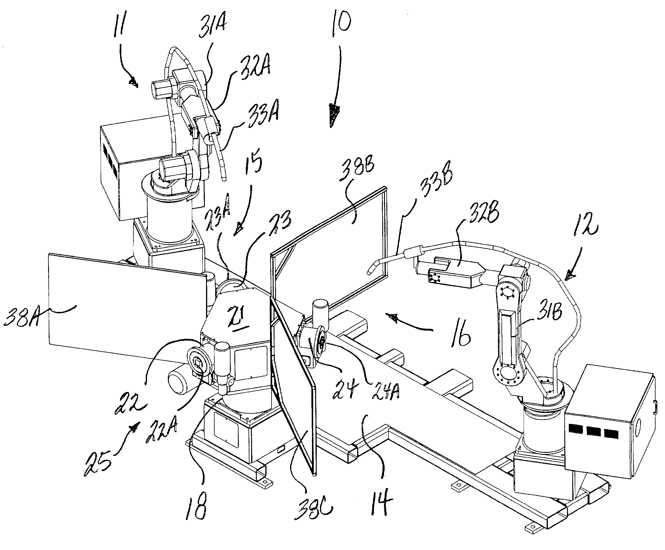
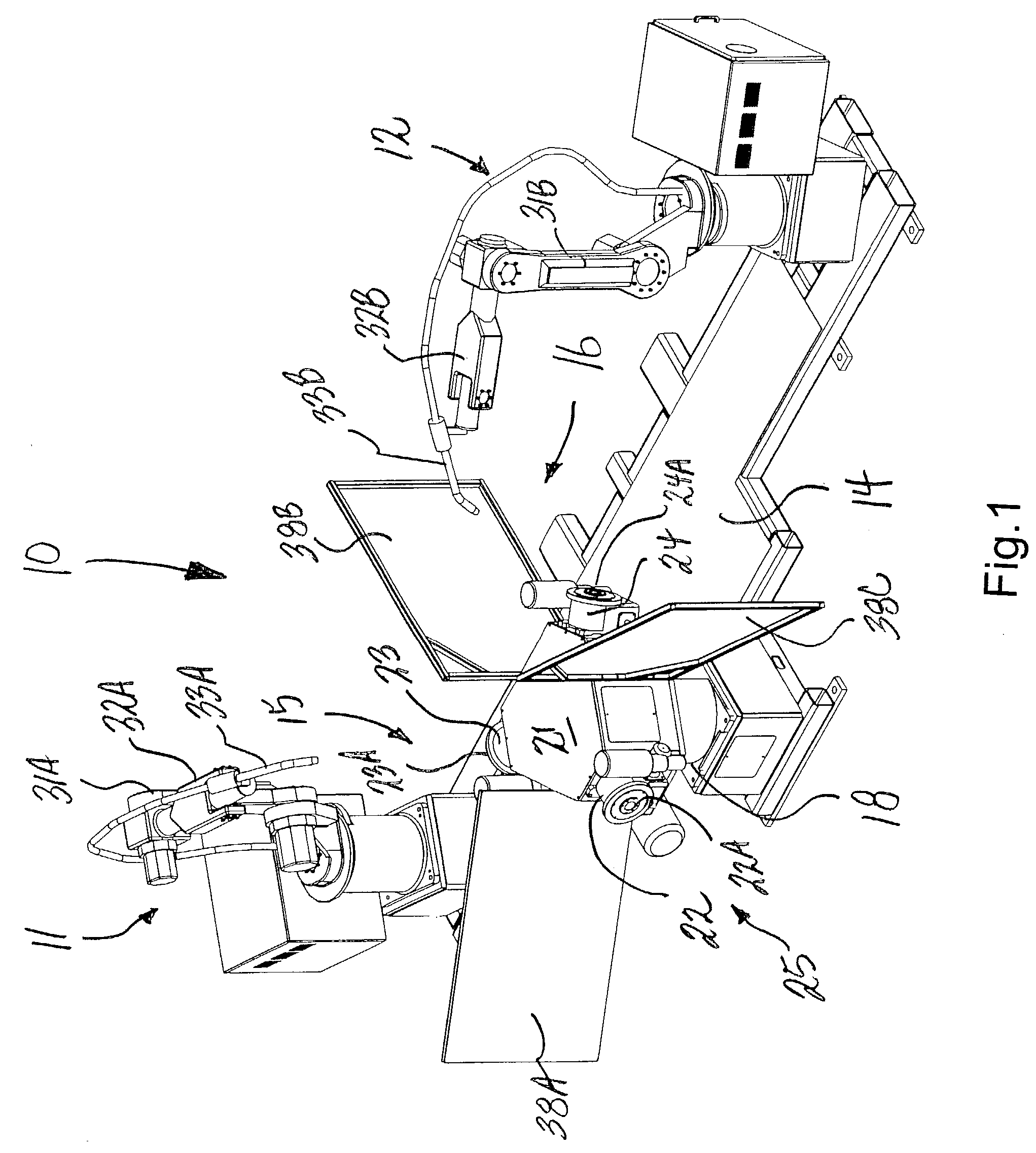
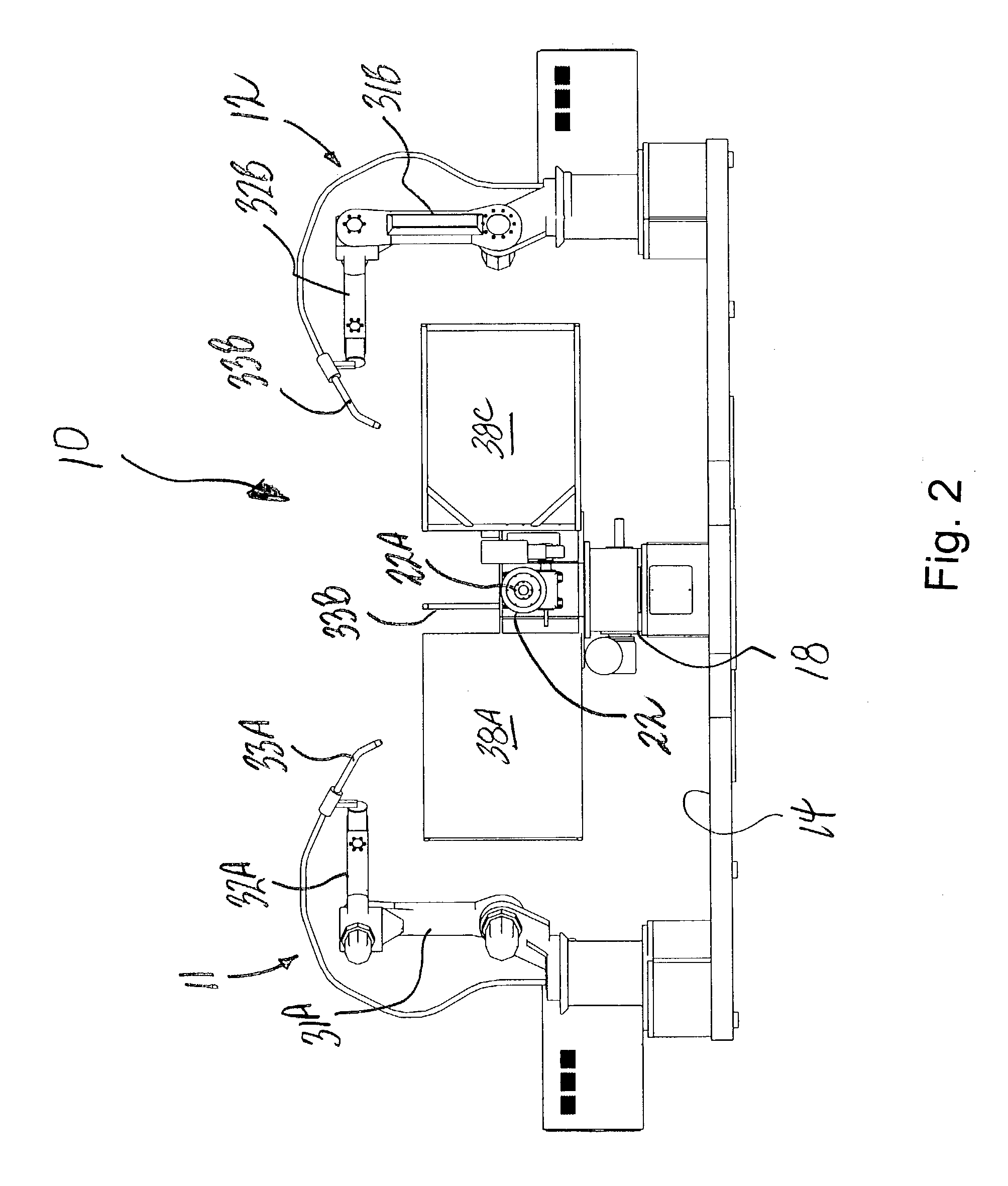
[0030] Referring now specifically to the drawings, a multi-station robotic welding assembly according to the present invention is illustrated in FIGS. 1-3, and shown generally at reference numeral 10. The assembly 10 is especially applicable in a production environment for welding items such as bumpers, foot plates, headlight supports, arm rests, and other components commonly used in all-terrain vehicles (ATVs) and golf carts. The assembly 10 includes first and second arc welding robots 11 and 12 attached to a common mounting platform 14 and located in respective weld stations 15 and 16. A rotatable fixture base 18 is mounted to the platform 14 between the robots 11, 12, and includes a junction box 21 and three indexers 22, 23, and 24 adapted for carrying respective fixtures used for holding workpieces to be welded. The fixtures "F" and "W" are illustrated in FIGS. 4-8, discussed below. Each fixture is custom designed and secured directly to a face plate 22A, 23B, and 24A of the indexer 22, 23, and 24 using a series of bolts and locating dowels. Individual components of the workpiece are loaded into the fixture at an operator's station 25 prior to welding, and are held in place by releasable clamps and holding devices. The mounting platform 14 provides a single common base for all components of the assembly 10, thus allowing convenient transport and relocation of the assembly without substantial disassembly or breaking down of parts.
[0031] Each of the robots 11 and 12 includes a movable arm 31A, 31B and wrist 32A, 32B adapted for carrying and manipulating a welding torch 33A, 33B. The robots 11, 12 are preferably manufactured by Fanuc Robotics of Rochester Hills, Mich., and sold under the trademark ARC Mate 100iB Robot. Each robot 11, 12 has a six-axis modular construction, and is electric servo driven for precision high-speed welding and cutting. The welding torch 33A, 33B is preferably a robotic, air-cooled MIG gun manufactured by Tregaskiss, Ltd. of Ontario, Canada, and sold as Model AC/QC 22.degree. 4' 0.035".
[0032] The rotatable fixture base 18 includes a three-position, DC driven, rotary cam indexer, such as that manufactured by Commercial Cam Co., Inc. (CAMCO) of Wheeling, Ill., and sold as Model #1305. The indexer has a cam-driven index drive which provides repeated movement of the fixture base 18 from one position to another, as indicated by arrow 36 in FIG. 3, thereby rotating the fixtures and attached workpieces between each of the two weld stations 15, 16 and the operator station 25. Typical cam-driven index drives have two basic elements: a cam attached to the input shaft (camshaft) and a follower wheel attached to the output shaft. As the cam rotates, followers on the follower wheel are guided through a path dictated by the shape of the cam. During part of the input rotation, the cam confines the followers (and therefore, the output) to a rigid, stationary position called "dwell." During the remainder of the camshaft rotation, the cam geometry causes the followers to move and the output to rotate, or "index". As the camshaft is rotated at a constant velocity, the output stops and starts (dwells and indexes) in a repeating pattern.
[0033] The indexers 22, 23, and 24 mounted to the junction box 21 and carrying the fixtures are preferably eight-position, DC driven, rotary cam indexers, such as that manufactured by CAMCO and sold as Model #601. Each indexer 22-24 moves the fixture and attached workpiece between eight different positions during welding in each of the welding stations 15 and 16. The fixture indexers 22-24 are spaced 120 degrees apart, such that each indexer locates a fixture and workpiece in each of the two weld stations 15, 16 and the operator station 25. Protective shields 38A, 38B, and 38C are arranged between the weld stations 15, 16 and the operator station 25 for shielding and protecting the surrounding area during welding. The junction box 21 contains a precision, high-performance, electro-deposited D-ring, or slip ring (not shown), such as that manufactured by the Kaydon Corporation. The D-ring provides continuous electrical connection of the indexers to a main control panel. Unlike conventional indexers which rotate clockwise and counterclockwise in a 180-degree path, the present D-ring allows continuous 360-degree rotation of the base indexer 18, thereby avoiding winding and breakage of cables inside the junction box 21.
[0034] Each weld robot 11 and 12 has an individual ground cable. The ground cables are mounted to a brass block that is mounted to a dedicated pneumatic cylinder. After indexing to the respective station 15, 16, the ground changes are automated through the taught program. The grounds are pushed up against the outer surface of the face plates of the indexers 22, 23, and 24, and remain up until the welding is completed. After welding, the grounds are lowered out of the way, so that the next fixture can be indexed into the weld station 15, 16.
[0035] Operation of the Robotic Welding Assembly
[0036] Referring to FIGS. 4-8, all stations of the robotic welding assembly 10 are initially empty prior to the operator's work shift. Customized fixtures "F" are mounted on respective indexers 22, 23, and 24 to accommodate the particular workpieces "W" to be welded, as shown in FIG. 4. Each indexer 22, 23, and 24 and fixture "F" cooperates to rotate the workpiece "W" between eight different positions during welding.
[0037] To begin the welding process, the operator activates the arc welding robots 11 and 12 located in the weld stations 15 and 16, respectively, and verifies the system programming applicable for the present shift. Programming for the robots 11, 12 is initiated to place the system in a complete automatic mode. The operator begins the shift by loading a first workpiece "W1" into the fixture "F1" at the operator station 25, as shown in FIG. 5. Once this fixture "F1" is loaded, the system program is initiated at a control panel. The fixture base 18 indexes approximately 120 degrees to move the first loaded workpiece "W1" directly in front of the robot 11 in the first weld station 15 for welding, as shown in FIG. 6. This action simultaneously moves the second fixture "F2" directly in front of the robot 12 in wait in the second weld station 16, and the fixture "F3" into the operator station 25 for loading. While robot 11 welds 50% of the workpiece "W1" in the first weld station 15, the operator loads a second workpiece "W2" into the fixture "F3". When robot 11 has completed welding at the first weld station 15, the fixture base 18 indexes to simultaneously move the second workpiece "W2" in front of robot 11 in the first weld station 15, the first workpiece "W1" in front of robot 12 in the second weld station 16, and fixture "F2" to the operator station 25 for loading. In the position shown in FIG. 7, the robot 11 welds 50% of the second workpiece "W2" in the first weld station 11, while robot 12 completes welding of the first workpiece "W1" in second weld station 16. At the same time, the operator loads a third workpiece "W3" into the fixture "F2" at the operator station 25. After welding is completed in both of the weld stations 15 and 16, the fixture base 18 indexes to simultaneously move the third workpiece "W3" in front of robot 11 in the first weld station 15, the second workpiece "W2" in front of robot 12 in the second weld station 16, and the first workpiece "W1" to the operator station 25 for unloading. In the position shown in FIG. 8, the operator unloads a completely assembled, welded workpiece "W1" from the fixture "F1" at the operator station 25, and then reloads the fixture "F1" with a fourth workpiece "W4". At the same time, robot 11 welds 50% of the third workpiece "W3" at the first weld station 15, while robot 12 completes welding of the second workpiece "W2" in the second weld station 16. This cycle continues for the remainder of the shift.
[0038] The above process maximizes operator production and efficiency by utilizing welding time to load and unload the fixtures "F" in the operator station 25. Moreover, the use of multiple robots substantially reduces the weld cycle time without requiring additional man power. With two robots 11, 12 welding 50% of the same workpiece "W", as described above, welding is completed 50% faster and at half the labor cost. The present assembly 10 requires less floor space than a standard two-robot weld cell; the required floor space being generally the same as that of a single robot cell.
[0039] A multi-station robotic welding assembly is described above. Various details of the invention may be changed without departing from its scope. Furthermore, the foregoing description of the preferred embodiment of the invention and best mode for practicing the invention are provided for the purpose of illustration only and not for the purpose of limitation-the invention being defined by the claims.