Emission control valve for gas-fueled engines

a technology of emission control valves and gas-fueled engines, which is applied in the direction of valve operating means/release devices, electric control, machines/engines, etc., can solve the problems of system and others like it being susceptible to performance deficiencies, not being particularly easy, convenient or economical to install, operate or use, and slow respons

Inactive Publication Date: 2004-07-22
CONTINENTAL CONTROLS CORP
View PDF10 Cites 39 Cited by
  • Summary
  • Abstract
  • Description
  • Claims
  • Application Information

AI Technical Summary

Problems solved by technology

While some have had varying degrees of success, they have primarily relied on various types of supplemental fuel metering, biasing of a pneumatic pressure regulator, or limited throttling of the main fuel supply and have required substantial amounts of external support equipment and electrical interconnections among such equipment, have suffered from slow response and generally have not been particularly easy, convenient or economical to install, operate or use.
This system and others like it are susceptible to the performance deficiencies of a pneumatic pressure regulator such as droop in the set point due to spring rate and/or hysterisis.
This type of system must wait for a subsequent change in the oxygen sensor reading before correcting for such errors, which results in a substantial time lag in engine response to load changes.
In this system, however, finite incremental variable control of flow is not possible; the system can operate only to fully open or fully close the poppet valve.
Such operation has limited resolution and turndown ratio and often results in instability in the regulated pressure, as exemplified in the patent in a test of a proportional-integral controller.
However, such non-stoichiometric engines emitted substantial exhaust pollutants.
As catalytic pollution emission systems became required on engines, the engines

Method used


Image

  • Emission control valve for gas-fueled engines
  • Emission control valve for gas-fueled engines
  • Emission control valve for gas-fueled engines

Examples


Embodiment Construction

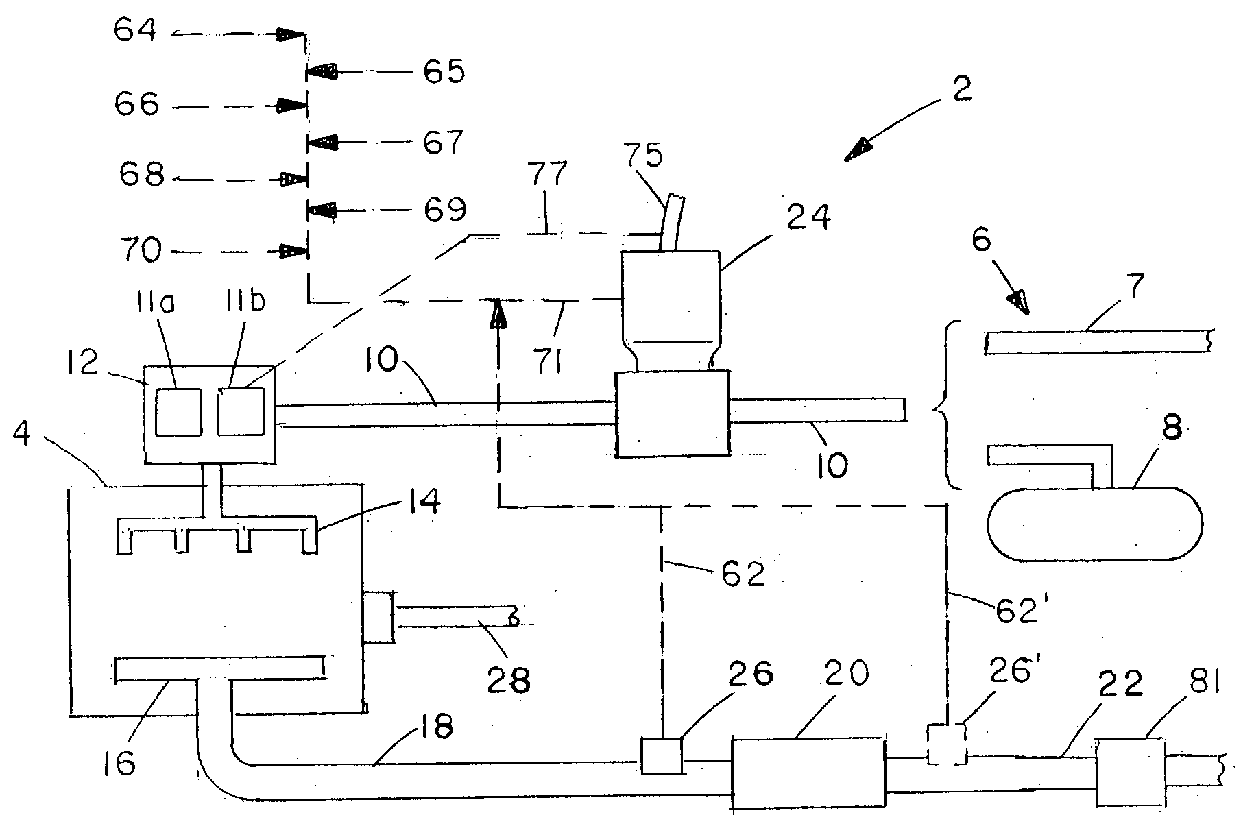
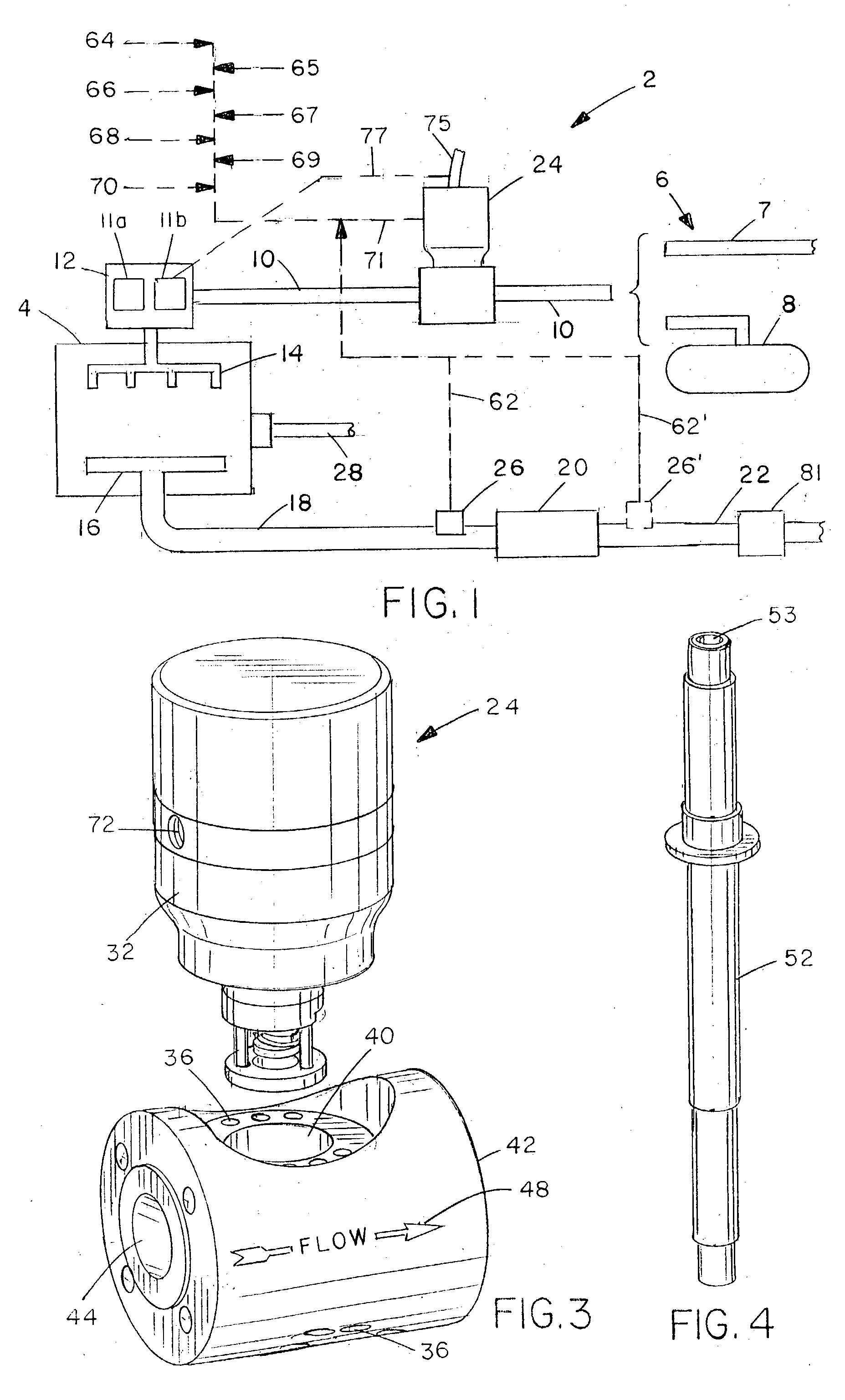
[0023] The invention herein can be best understood by reference to the drawings. FIG. 1 illustrates schematically a gas-fueled engine system 2 in which the emission control valve of the present invention is incorporated. The gaseous fuel used in the engine may be any gaseous fuel including gaseous hydrocarbons and hydrogen, but will commonly be municipal natural gas, landfill gas, butane or propane; such engines typically run on a stoichiometric, air / fuel mixture, but can be used with clean-burn engines (large amount of excess air). The invention is not applicable to liquid fuel engine systems. In the system 2 there is an internal combustion engine 4. The fuel which is obtained from a gas fuel supply source 6 which may be a municipal natural gas supply system or landfill gas 7, a propane or butane supply tank 8, or any other convenient source of gaseous fuel. The gaseous fuel for the engine 4 moves under pressure through fuel supply conduit 10 to the air / fuel mixing system 12, which...


PUM


Abstract

An emission control device for use with stationary or mobile gas-fueled internal combustion engines is described, which is placed in the fuel supply line and operates with full fuel authority. An oxygen sensor measures exhaust oxygen content. The valve internally houses a programmable microprocessor, a pressure transducer and a fuel flow conduit throttled by a balanced poppet valve. Signals to the microprocessor from the oxygen sensor, the pressure transducer indicating outflow gas pressure cause the microprocessor to motivate an actuator to move the valve within the gas stream and thus regulate the outlet pressure and also the gas flow rate to maintain a desired air/fuel ratio to the engine and keep exhaust emissions at an optimum level consistent with the engine operating load requirements and characteristics. Finite incremental control of valve position, preferably assisted by an internal position transducer, permits close control of the exhaust emissions.

Description

[0001] 1. Field of the Invention[0002] The invention relates to emission control valves for gas-fueled engines, both carbureted and fuel injected. More particularly it relates to an emission control valve with direct emissions sensor input having internal control and full fuel authority without supplemental fuel metering or biasing of a pneumatic pressure regulator.[0003] 2. Background Information[0004] Emission control devices and methods for use with stationary or mobile engines are numerous and extensively described in prior art patents and literature. Such devices can be separated into two major groups based on their respective fuels. The two groups represent significantly different areas of technology, notwithstanding their common goal, since the structure and operational characteristics of the two types of applications are quite different. One group is those that are fueled with a liquid fuel, such as gasoline or diesel fuel; that group is not involved in the present invention...

Claims


Application Information

Patent Timeline
IPC IPC(8): F02D19/02F02D41/00F02D41/14F02D41/30F02M21/02
CPCF02D41/0027F02D41/1454F02D41/3005F02M21/047Y02T10/32F02D19/027F02M21/0212F02M21/0215F02M21/0239F02D19/023F02M21/0206Y10T137/7761Y02T10/30
Inventor FISHER, C. ROSSFISHER, DAVID G.YATES, KRISTIAN W.HOIE, WILLIAM A.
Owner CONTINENTAL CONTROLS CORP
Why Eureka
Try Eureka