Method of operating hydrokinetic torque converters in the power trains of motor vehicles and torque converter for the practice of the method
- Summary
- Abstract
- Description
- Claims
- Application Information
AI Technical Summary
Benefits of technology
Problems solved by technology
Method used
Image
Examples
Embodiment Construction
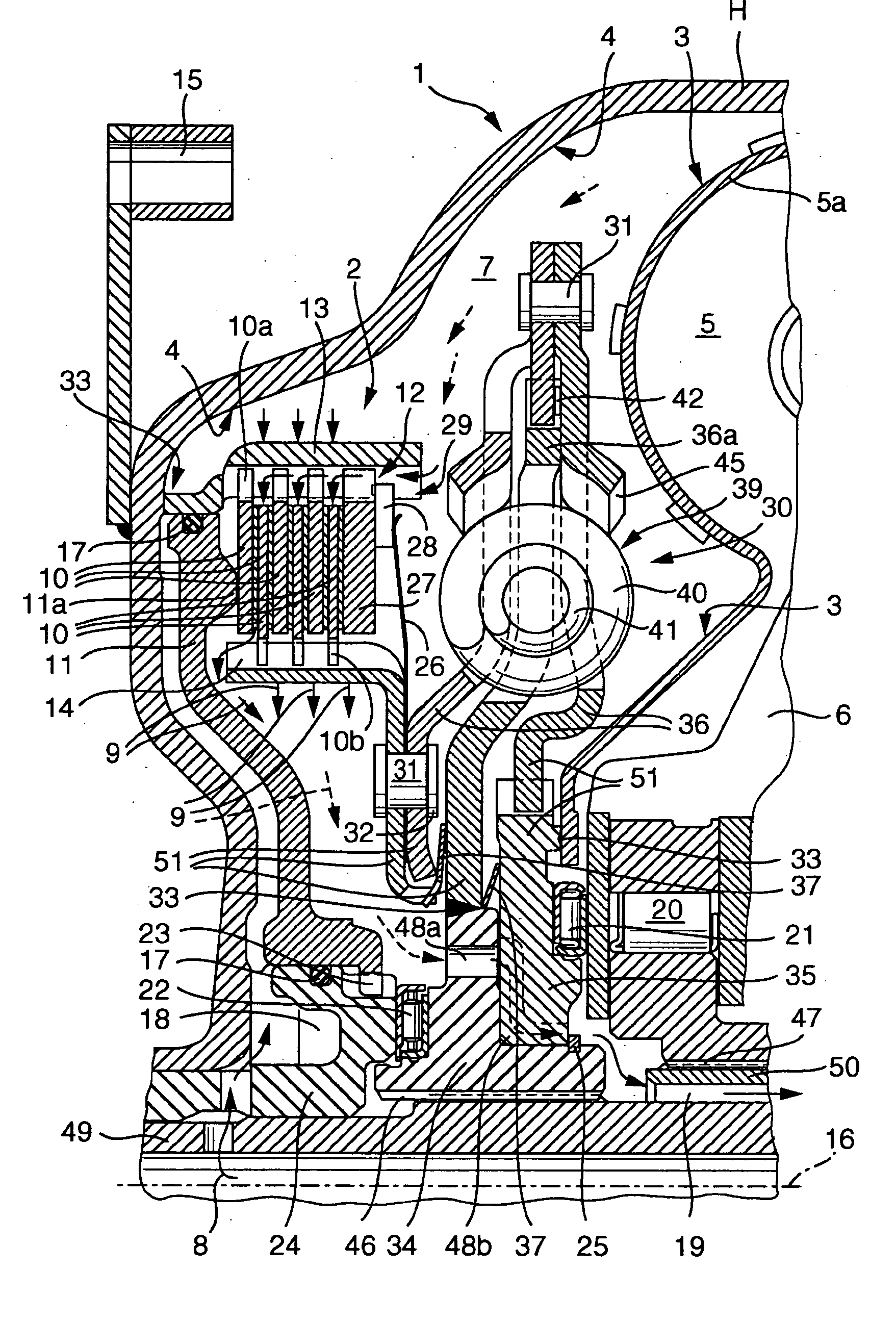
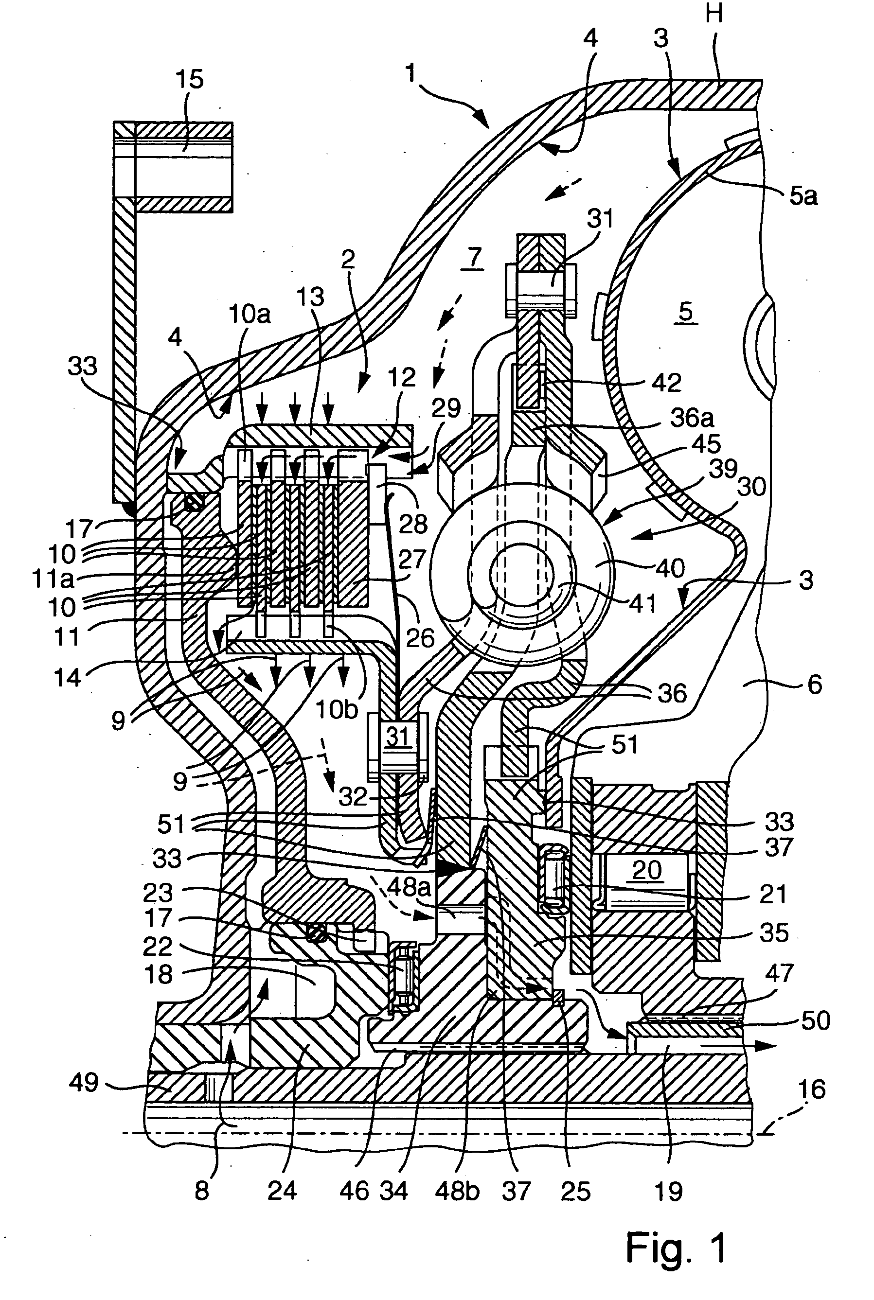
[0055] FIG. 1 illustrates certain details of a hydrokinetic torque converter 1 which is assumed to be installed in the power train of a motor vehicle, namely between the output member (such as a crankshaft or a camshaft) of a non-illustrated prime mover (e.g., an internal combustion engine or a hybrid drive) and the input shaft 49 of a change-speed transmission, not shown. The housing H of the torque converter 1 is rotatable about an axis 16 which coincides with the axis of the input shaft 49. The means for rotating the housing H includes at least one connector 15 which is rotatable with the output member of the prime mover. It will be seen that FIG. 1 is not a true engineering drawing because it shows only those portions of various component parts which are located in the plane including the axis 16; such illustration is believed to be optimally suited to properly depict the relevant component parts of the improved torque converter 1.
[0056] The connector 15 can be secured to a flyw...
PUM
 Abstract
Description
Claims
Application Information
 - R&D
- Intellectual Property
- Life Sciences
- Materials
- Tech Scout
- Unparalleled Data Quality
- Higher Quality Content
- 60% Fewer Hallucinations
Browse by: Latest US Patents, China's latest patents, Technical Efficacy Thesaurus, Application Domain, Technology Topic, Popular Technical Reports.
© 2025 PatSnap. All rights reserved.Legal|Privacy policy|Modern Slavery Act Transparency Statement|Sitemap|About US| Contact US: help@patsnap.com


