

Electro-optical glazing structures having scattering and transparent modes of operation and methods and apparatus for making the same
Inactive Publication Date: 2004-08-19
LI LE +2
View PDF9 Cites 79 Cited by
- Summary
- Abstract
- Description
- Claims
- Application Information
AI Technical Summary
Benefits of technology
[0036] Accordingly, a primary object of the present invention is to provide an electro-optical glazing structure which avoids the shortcomings and drawbacks of prior art technologies.
[0037] Another object of the present invention is to provide an electro-optical glazing structure which has total-scattering and total-transmission modes of operation for improved control over the flow of electromagnetic radiation within the solar region of the electromagnetic spectrum (i.e. Solar Spectrum).
Problems solved by technology
While conventional forms of glazing serves many useful functions, such forms are not without problems.
While electromagnetic radiation is broad-band in nature, it is the ultraviolet light component thereof which causes molecular decomposition in various types of plastic material and inorganic dyes, which results in color fading.
The energy transmitted through the glass window is typically absorbed by furnishings or structures within the interior environment, and often becomes trapped therewithin causing an increase in interior temperature.
However, as window blind is mounted within the interior of the building transportation environment, electromagnetic radiation is allowed transmit through the window, raises the temperature within the internal environment, and thus increases thermal loading on cooling systems during the hot weather season.
Also, the operation of window blinds requires mechanical or electromechanical controls which tend to be bulky and expensive to manufacture, install and maintain.
The major disadvantages thereof are reduction in interior light, loss of visibility, and extra care required in cleaning.
Moreover, prior art electromagnetic window films are incapable of changing from transmissive during winter months to reflective during summer months in order to effectively use electromagnetic radiation for dynamic temperature control of biological environments (e.g. human habitats, greenhouses and the like).
Consequently, during heating seasons, such glass fails to lessen the thermal loading on the heating systems of such buildings, as would be desired in an effort to conserve energy and heating resources during the winter months.
This, however, results in high optical loss, as up to 60% of the incident light is absorbed by the polarizers, in the desired non-blocking mode of operation.
While a smart window structure based on polymer dispersed liquid crystal (PDLC) technology offers better performance than TN or STN based window structures, such smart window structures suffer from several significant shortcomings.
However, the electrochromic device suffers from slow response time and shorter life-time.
However, this technology has a problem associated with the settling of the metal particles due to gravity.
The main disadvantage of the PDLC technology is the inherent haze caused by the optical index mismatching, particularly at large viewing angles.
The second problem associated with prior art PDLC technology is its high cost of manufacture.
Due to the extremely high price of manufacture, such manufacturers are facing significant obstacles in expanding the PDLC privacy window market.
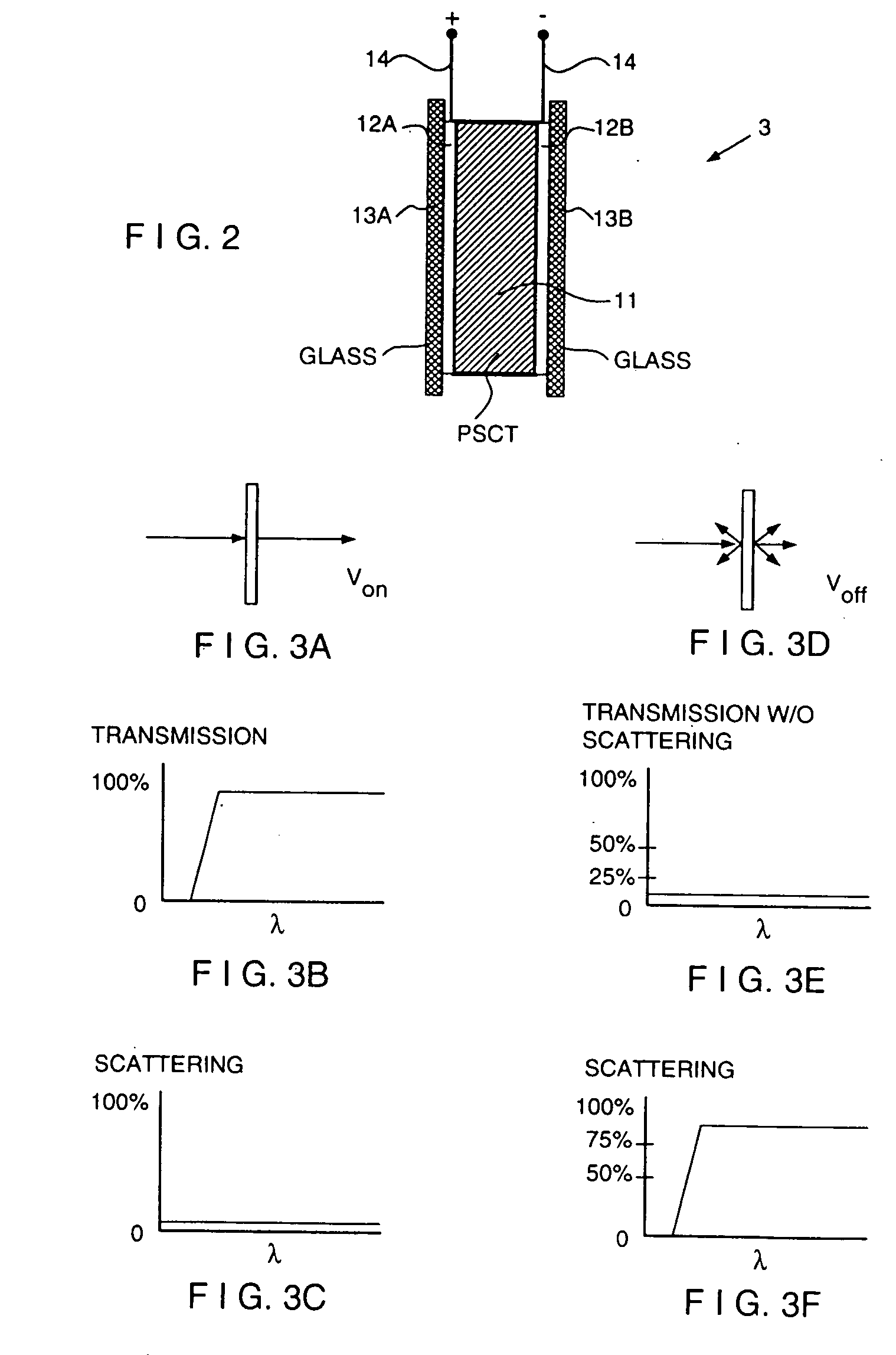
Prior art PSCT technology has at least five significant problems which hitherto have neither been addressed or solved in a satisfactory manner.
Therefore, the cost of such a liquid crystalline polymer becomes extremely high, making the price of the PSCT device even higher than that of the PDLC.
Secondly, in typical PSCT systems, since monomers with mesogenic groups are used, the formation of the polymer network will partially alter the orientational order at each cross-linking site.
Such a field often brings about electric shorting problems.
However, the liquid crystal molecules close to the polymer, network will not respond to a modest switching field, resulting in strong haze, particularly at large oblique angles.
Thirdly, scaling-up the panel size of PSCT-based devices has been very difficult in practice.
Fourthly, making a large-size uniform PSCT device is difficult because this lamination method cannot be used.
However, when filling liquid crystal into a large size panel, the flow streaks of the liquid crystal and polymer mixture induce readily noticeable marks.
Therefore, the resulting PSCT device appears very non-uniform.
Finally, the cost of glass substrates with conductive Tin Oxide layer coatings is very expensive when using PSCT-based technology.
Also, the cost of plastic substrates with conductive Tin Oxide layer coatings is very expensive when using PDLC technology.
Such factors contribute to the high price of electro-optical devices based on PDLC and PSCT technologies.
Method used
View moreImage
Smart ImageViewing Examples

Examples
example 1
[0111]
1 Ingredient Function % Weight(mg) Poly(dimethylsiloxane) Surfactant 0.01 0.1032 2,6-Di-tert-butyl-4 Photo Initiator 0.0029 0.03 methylphenol P9615A Nematic 89.781 926.3 CB15 Chrial 7.1821 74.1 EGD Monomer 3.024 31.2
example 2
[0112]
2 Ingredient Function % Weight(mg) Poly(dimethylsiloxane) Surfactant 0.01 0.1021 2,6-Di-tert-butyl-4 Photo Initiator 0.002 0.02 methylphenol E44 Nematic 91.125 930.5 CB15 Chrial 6.4929 66.3 EGD Monomer 2.3699 24.2
example 3
[0113]
3 Ingredient Function % Weight(mg) Poly(dimethylsiloxane) Surfactant 0.01 0.10959 IG500 Photo Initiator 0.1277 1.4 P9615A Nematic 90.09 987.4 CB15 Chrial 7.2627 79.6 EGD Monomer 2.5091 27.5
Login to View More PUM
| Property | Measurement | Unit |
|---|---|---|
| Fraction | aaaaa | aaaaa |
| Fraction | aaaaa | aaaaa |
| Fraction | aaaaa | aaaaa |
Abstract
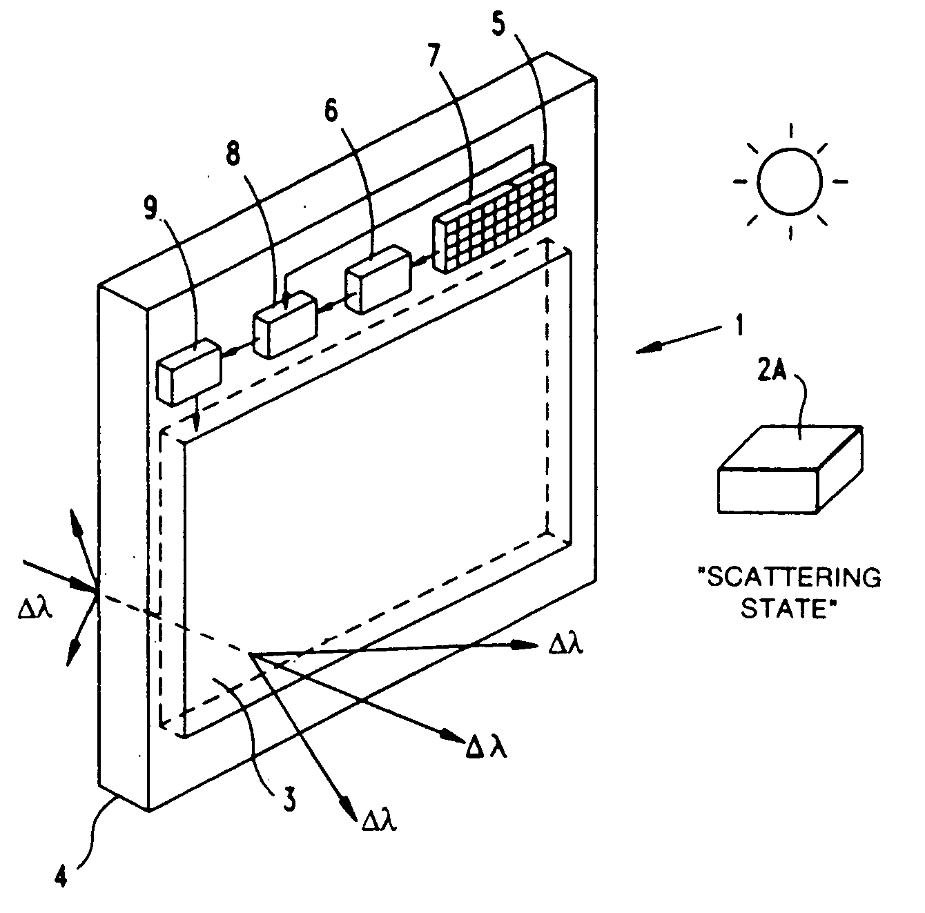
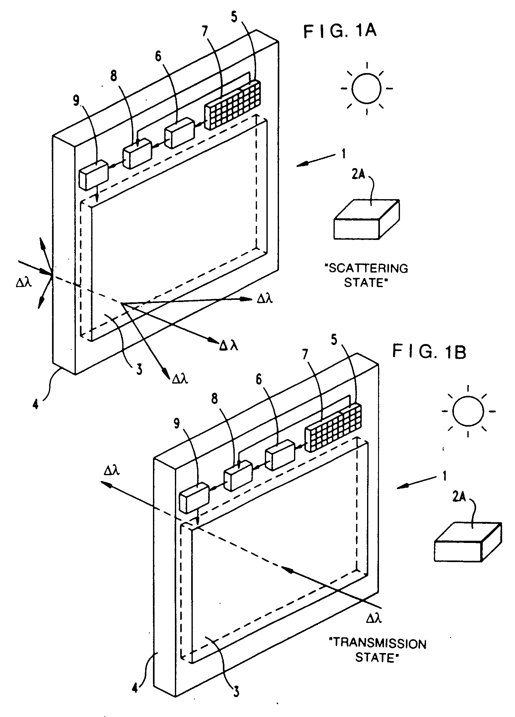
Electro-optical glazing structures having total-scattering and total-transparent modes of operation which are electrically-switchable for use in dynamically controlling electromagnetic radiation flow in diverse applications.
Description
RELATED CASES[0001] This is a Continuation-in-part of: copending application Ser. No. 09 / 287,579 entitled "Electro-Optical Glazing Structures Having Scattering And Transparent Modes Of Operation And Methods And Apparatus For Making The Same" filed Apr. 6, 1999; which is a Continuation-in-part of copending application Ser. No. 09 / 032,302 entitled "Electro-Optical Glazing Structures Having Reflection And Transparent Modes Of Operation" filed Feb. 27, 1998; which is a Continuation-in-part of application Ser. No. 08 / 805,603 entitled "Electro-Optical Glazing Structures Having Total-Scattering And Transparent Modes of Operation For Use In Dynamical Control Of Electromagnetic Radiation" filed Feb. 26, 1997, now U.S. Pat. No. 5,940,150; application Ser. No. 08 / 739,467 entitled "Super Broadband Reflective Circularly Polarizing Material And Method Of Fabricating And Using Same In Diverse Applications", by Sadeg M. Faris and Le Li filed Oct. 29, 1996, now U.S. Pat. No. 6,034,753; which is a Co...
Claims
Login to View More Application Information
Patent Timeline
 IPC IPC(8): C09K19/54E06B9/24F24J2/40G02B5/30G02F1/1334G02F1/1335G02F1/13357G02F1/1347G02F1/137G02F1/139
CPCC09K19/544E06B9/24E06B2009/2464F24J2/407G02B5/3016G02F1/1334Y02E10/40G02F1/13362G02F1/13471G02F1/13718G02F1/1393G02F2001/133543Y02B10/20G02F1/133536F24S50/80G02F1/133543
InventorLI, LELI, JIAN-FENGFARIS, SADEG M.
OwnerLI LE