Method and apparatus for manufacturing a custom fit optical display helmet

a technology of optical display and manufacturing method, which is applied in the field of manufacturing methods of helmets, can solve the problems of total visual loss of optical display, adversely affecting the center of gravity (cg) of typical flight helmets, and the addition of substantial mass of optical display systems

Active Publication Date: 2004-08-26
CREW SYST CORP
View PDF9 Cites 43 Cited by
  • Summary
  • Abstract
  • Description
  • Claims
  • Application Information

AI Technical Summary

Benefits of technology

[0015] It is a related object to position the pilot's eyes within the helmet so that the eyes are aligned with pre-positioned optics mounted on the helmet, so that only minimal (if any) adjustments to the optics are necessary.
[0016] It is a further object to provide an apparatus for determining the precise position of the subject's pupils with respect to a 3-D model of the subject's head, thereby facilitating manufacture of the helmet.
[0020] The vertical compliance of the CFPL is limited to less than the thickness of the comfort foam; the rest of the system is incompressible under normal operational loads. The CFPL is thusly capable of maintaining proper eye locus under maximally high Gz conditions.
[0021] The fact that the CFPL conforms to the shape of the head over a large surface area has other advantages. The pressure against the head is both uniform and minimum, eliminating so-called hot spots and maximizing comfort. Typical non-spherical head shapes provide great stability against rotational forces, and also allow a comfortable fit only with the head in the location built into the CFPL, assuring proper eye positioning. According to one embodiment of the method according to the invention, the CFPL is implemented by laser scanning the subject's head with eyes open (e.g. by using a Class 1 laser, which is safe for indefinite exposure) while wearing a thin close-fitting skull cap for hair compression. A marker indicating the subject's approximate preferred horizontal line of sight head orientation is included in the scan. The resulting 3-D head model is CAD-manipulated to add a small constant offset (a few mm) over the entire CFPL contact area to allow for the comfort foam and cover between the EA material and the head. This expanded head is subtracted from a CAD model of an EA component such that the head cutout is properly positioned with respect to the outer helmet-matching surface. A standard trim edge is adjusted if necessary for subject-specific earcup location needs. The result is a final EA liner CAD model that is transferred to CNC software for tool path generation and machining to final shape. This can be done from rectangular blocks of rigid EA foam, or from EA foam blanks molded such that the outer surface is near net shape to minimize machining time. Over predefined areas of the EA's outer surface material not required for impact protection is removed; this minimizes mass for heads smaller than the largest that will fit within that liner size. The comfort foam and cover are then added to the machined EA foam's inner surface, forming a complete CFPL.
[0022] The CFPL according to the invention offers numerous advantages over optical helmet fitting / suspension systems according to the prior art, including maximum comfort, maximum stability under both +Gz and rotational forces, minimum mass, and precise eye to optics positioning.
[0023] Further, the CFPL is adaptable to any helmet configuration, can easily incorporate ventilation features, and is readily adaptable to varying impact protection requirements by changing the EA material and or / the minimum thickness of the EA material.

Problems solved by technology

Optical display systems have added substantial mass to and adversely affected the center of gravity (CG) of typical flight helmets.
In either case, the added mass and adverse CG effects due to the optics leads to very large forces tending to shift the helmet location on the head during high-G aircraft maneuvers; the shift at +9 Gz is commonly great enough to cause total visual loss of the optical display.
However, due to comfort-induced pressure limitations and the inability to eliminate vertical slack in the system (because of the relatively low weight of the helmet and optics at +1 Gz as compared to +9 Gz), vertical helmet motion due to the suspension tightening under the force of the 9-times increase in the helmet's weight at +9 Gz cannot be prevented.
However system elasticity and concentrated pressure points contribute to helmet motion and therefore to difficulty in maintaining the position of the optics relative to the eyes under high loads.
However the performance was still less than ideal.
U.S. Pat. No. 6,487,786 discloses a method and a tool for aligning a helmet with respect to a wearer's head in the above described systems, but does not solve the problem of relative motion between the helmet and the wearer's head under high G forces.
However, it cannot compensate for helmet movement under G-forces.
Also, many current optical systems are not adjustable, for reasons of availablespace, complexity, mass, and tolerances inherent in adjustment systems.
The vertical compliance of the CFPL is limited to less than the thickness of the comfort foam; the rest of the system is incompressible under normal operational loads.
(1) There is considerable variation in laser classification standards internationally, as well as much disagreement as to which classifications represent "eye-safe" lasers.
(2) Many pilots will refuse to be scanned with eyes open regardless of the laser classification.
(3) Because of the optical reflective characteristics of the eye, neither the corneal surface nor the pupil are defined in an eye-open scan with the precision and accuracy sufficient for an optimum CFPL.

Method used


Image

  • Method and apparatus for manufacturing a custom fit optical display helmet
  • Method and apparatus for manufacturing a custom fit optical display helmet
  • Method and apparatus for manufacturing a custom fit optical display helmet

Examples


Embodiment Construction

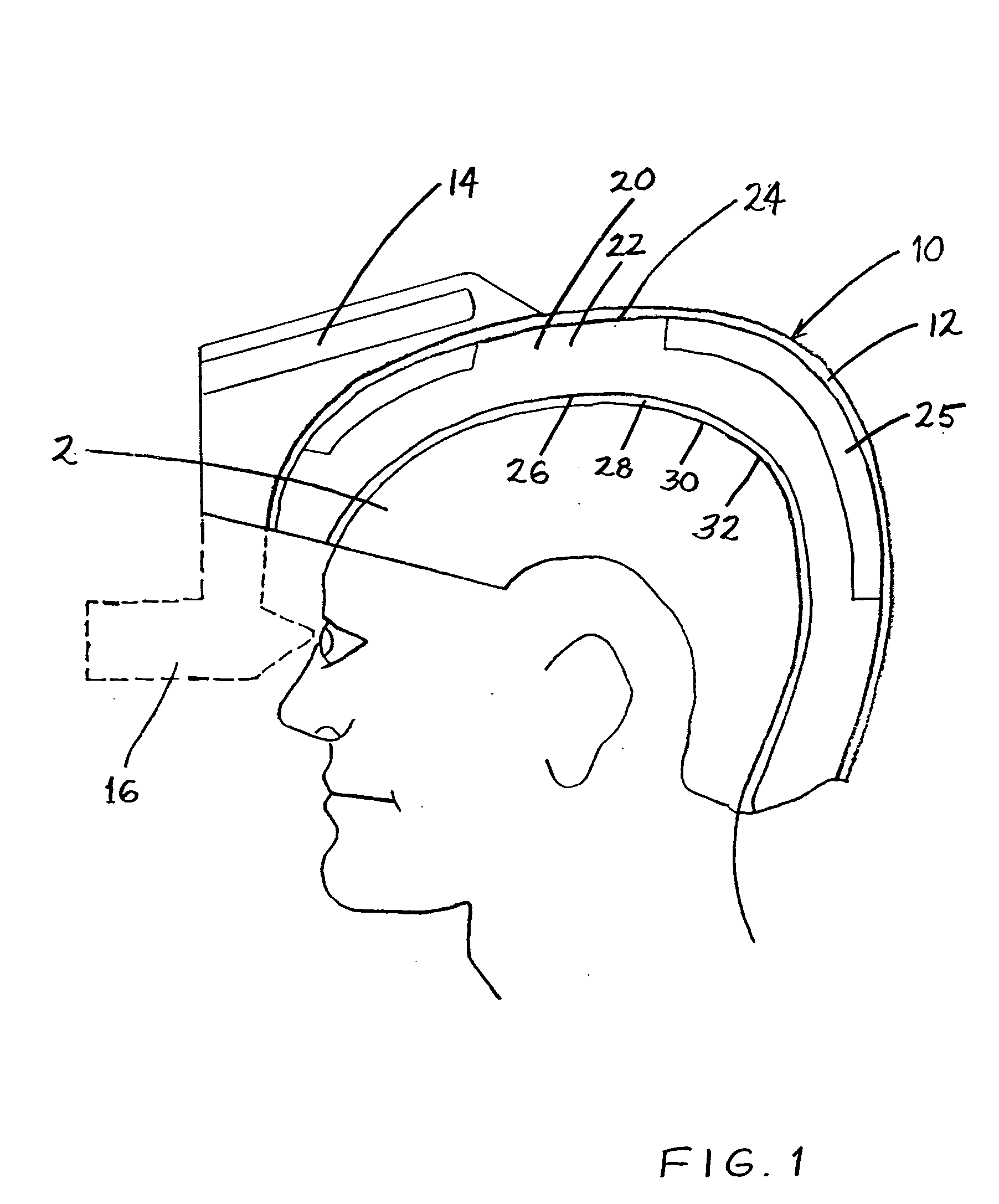
[0039] FIG. 1 shows a subject's head 2 fitted with a helmet 10 comprising a helmet shell 12 provided with electronics and / or optics 14 for projecting an image onto a visor, or optics 16 which are aligned with the subject's eyes when the helmet 10 is in place. This alignment is achieved with a custom-fit protective liner 20 which brings the subjects eyes into alignment with and the proper distance from the visor image or the optics 16, without the need for adjusting the position of the optics with respect to the helmet shell 12.

[0040] The custom-fit protective liner 20 includes a block of energy absorbing material 22 having an outer surface 24 which forms the outer surface of the protective liner, and an inner surface 26 which is offset from the subject's head by a constant distance which is compensated by a layer of comfort foam 28 and a cover 30 having a collective thickness substantially equal to the offset. The cover 30 therefore has an inner surface 32 which forms the inner surf...


PUM

PropertyMeasurementUnit
acute angleaaaaaaaaaa
radiusaaaaaaaaaa
look-down angleaaaaaaaaaa

Abstract

A helmet with an optical display system is provided with a custom fit protective liner which precisely aligns the wearer's eyes with the optics on the helmet. The helmet is manufactured by positioning the subject's head in a fixture; determining the position of the subject's pupils with respect to the fixture; scanning the subject's head with a laser while positioned in the fixture in order to obtain a 3-D model of the subject's head; and providing a helmet liner having an outer surface which is profiled to position it inside a helmet shell. The position of the subject's pupils may be determined by scanning pupil locating features of the fixture. The 3-D model is then used to provide the helmet liner with an inner surface which conforms to the subject's head and is positioned with respect to the outer surface so that the outer surface will have a predetermined position with respect to the subject's pupils. The helmet liner is then fitted in the helmet shell to form a helmet. The helmet shell may thus be fitted with pre-positioned optics which are properly positioned with respect to the subject's pupils.

Description

PRIORITY CLAIM[0001] This application claims priority under 35 U.S.C. .sctn.119 from U.S. Provisional Application Serial No. 60 / 449,782 which was filed on Feb. 25, 2003.[0002] 1. Field of the Invention[0003] The invention relates to a method for manufacturing a helmet, in particular for a pilot, wherein the helmet carries optics which must be precisely aligned with the pilot's eyes and must remain aligned when the helmet is subject to large forces. The invention also relates to an apparatus for determining the precise positioning of a subject's pupils with respect to a 3-D model of the subject's head.[0004] 2. Description of the Related Art[0005] Optical display systems have added substantial mass to and adversely affected the center of gravity (CG) of typical flight helmets. At the same time, positioning and alignment of the optical system with respect to the user's eyes is very critical; the usable region of eye locus around the design position may be less than a 5 mm radius hemis...

Claims


Application Information

Patent Timeline
Patent Type & Authority Applications(United States)
IPC IPC(8): A42C2/00A61B5/107G02B27/01
CPCA42C2/007A61B5/0064Y10T29/49769G02B27/017Y10T29/53087A61B5/1077A42B3/04A42B3/12A42C2/00
Inventor PIORKOWSKI, GARY J.RADZELOVAGE, WILLIAM
Owner CREW SYST CORP
Why Eureka
Try Eureka