Storage phosphor panel, radiation image sensor and methods of making the same

a technology of radiation image sensor and storage phosphor, which is applied in the direction of x-ray/infra-red process, photographic process, coating, etc., can solve the problems of prone to physical damage of phosphor panels, inability to use production methods in order to produce high-quality screens, and brittle needle-shaped phosphors, etc., to achieve remarkable improvement of the moisture resistance of the storage phosphor layer

Inactive Publication Date: 2004-08-26
T2PHARMA GMBH
View PDF16 Cites 29 Cited by
  • Summary
  • Abstract
  • Description
  • Claims
  • Application Information

AI Technical Summary

Benefits of technology

0107] Since the storage phosphor panel of the present invention has a transparent inorganic film formed on the first transparent organic film covering over the storage phosphor panel, the moisture resistance of the storage phosphor layer can remarkably be improved by coating one or more transparent inorganic film thereupon.
0108] In the case wherein an outermost organic film is further formed on the transparent inorganic film layer or layers, this transparent organic film may prevent the transparent inorganic film from peeling after frequent use.

Problems solved by technology

However, this production method can not be used in order to produce high quality screens with every arbitrary phosphor available.
Unfortunately such needle shaped phosphors are quite brittle and the phosphor panels are prone to physical damage after only a few cycles in the scanning apparatus.

Method used


Image

  • Storage phosphor panel, radiation image sensor and methods of making the same

Examples


Embodiment Construction

[0110] Preparation of the Phosphor Screens

[0111] CsBr:Eu phosphor screen layers were coated by thermal vapor deposition of CsBr and EuOBr.

[0112] Therefore CsBr was mixed with EuOBr and placed in a container in a vacuum deposition chamber. The phosphor was deposited on an aluminum substrate having a thickness of 1.5 mm and a circular diameter of 40 mm.

[0113] The distance between the container and the substrate was 10 cm. During vapor deposition the substrate was rotated at a velocity of 12 rpm.

[0114] Before starting evaporation, the chamber was evacuated to a pressure of 4.10.sup.-5 mbar. During the evaporation process Ar was introduced as an inert gas in the chamber.

[0115] Several screens were produced in order to provide a test material suitable for test with several differing protective coating application techniques.

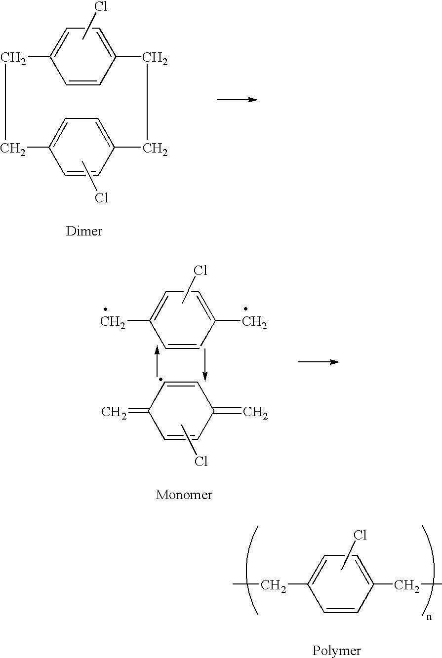
[0116] Parylene C was applied on a phosphor screen by a low-temperature, low-pressure application technique. The dimer chloro-di-para-xylylene was evaporated at 150.d...


PUM

PropertyMeasurementUnit
thicknessaaaaaaaaaa
thicknessaaaaaaaaaa
temperatureaaaaaaaaaa

Abstract

A stimulable phosphor adapted to convert incident radiation into visible light is formed on one surface of a substrate in a storage phosphor panel, wherein surfaces of phosphor and, optionally, the said substrate, are covered with a poly-paraxylylene film, whereas a film-forming silazane or siloxazane type polymeric compound covers the outermost surface of the poly-paraxylylene film on the phosphor side.

Description

[0001] The application claims the benefit of U.S. Provisional Application No. 60 / 455,240 filed Mar. 17, 2003.[0002] The present invention relates to a storage (stimulable) phosphor panel suitable for use in medical X-ray radiography, and a method of making them.[0003] A well known use of storage phosphors is in the production of X-ray images. In U.S. Pat. No.3,859,527 a method for producing X-ray images with a photostimulable phosphor, which are incorporated in a panel, is disclosed. The panel is exposed to an incident pattern-wise modulated X-ray beam and as a result thereof the phosphor temporarily stores energy contained in the X-ray radiation pattern. At some interval after the exposure, a beam of visible or infra-red light scans the panel in order to stimulate the release of stored energy as light that is detected and converted to sequential electrical signals which become processed in order to produce a visible image. For this purpose the phosphor should store as much as possi...

Claims


Application Information

Patent Timeline
Patent Type & Authority Applications(United States)
IPC IPC(8): C09K11/77G03B42/08G21K4/00
CPCC09K11/7733C09D183/16C08G77/62G21K4/00
Inventor BERGH, RUDY VAN DENCABES, TOM
Owner T2PHARMA GMBH
Why Eureka
Try Eureka