Enhanced boolean processor

Inactive Publication Date: 2004-09-09
JUNIVERSITI OF NORT KAROLINA EHT SHARLOTT
View PDF6 Cites 7 Cited by
  • Summary
  • Abstract
  • Description
  • Claims
  • Application Information

AI Technical Summary

Benefits of technology

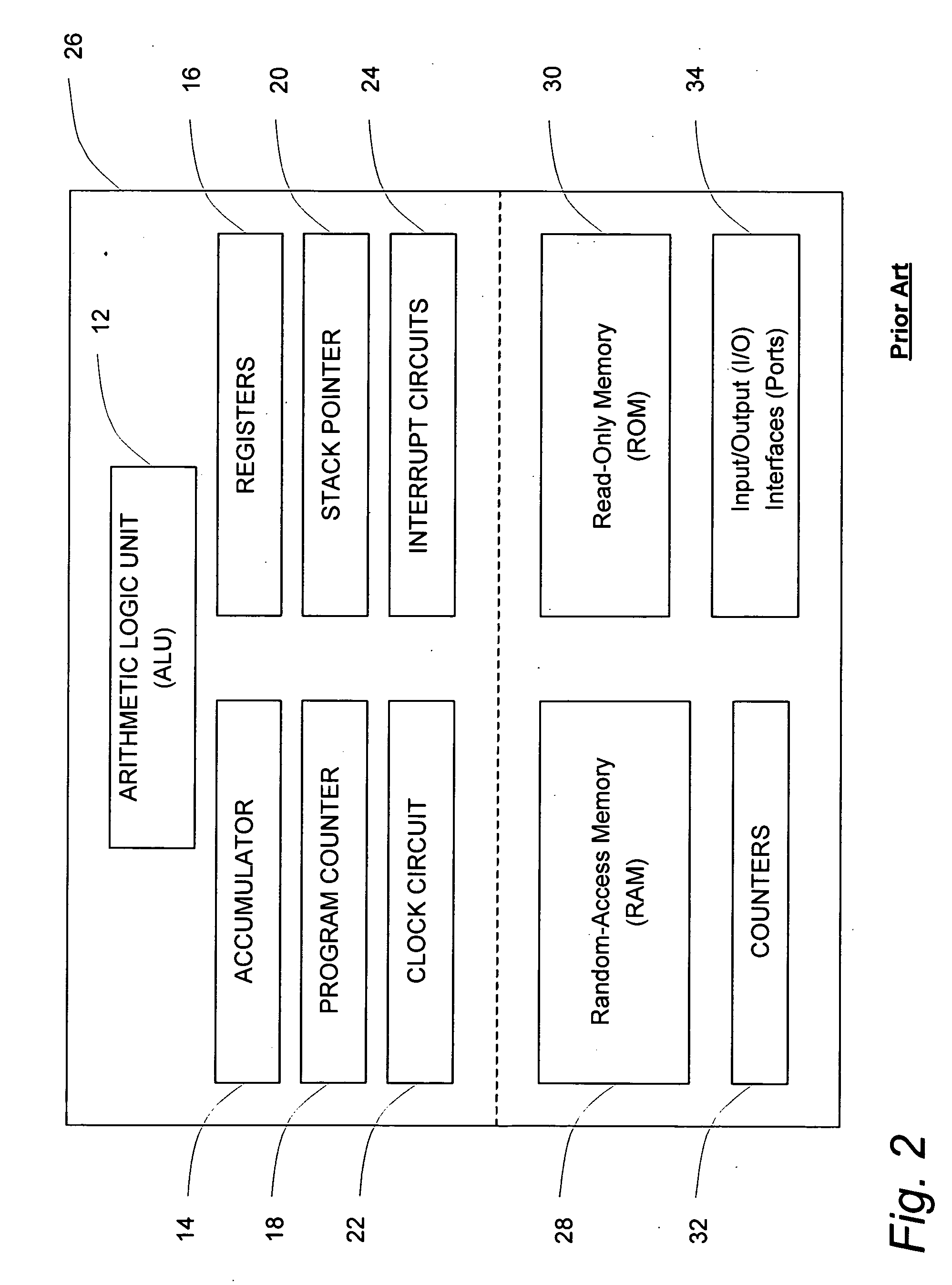
0023] Embodiments of the general-purpose Boolean processor of the present invention incorporate an architecture that is designed to provide optimal performance for computing complex Boolean expressions. The Boolean processor is intended for use in, among other things, monitoring and automation applications. The Boolean processor is

Problems solved by technology

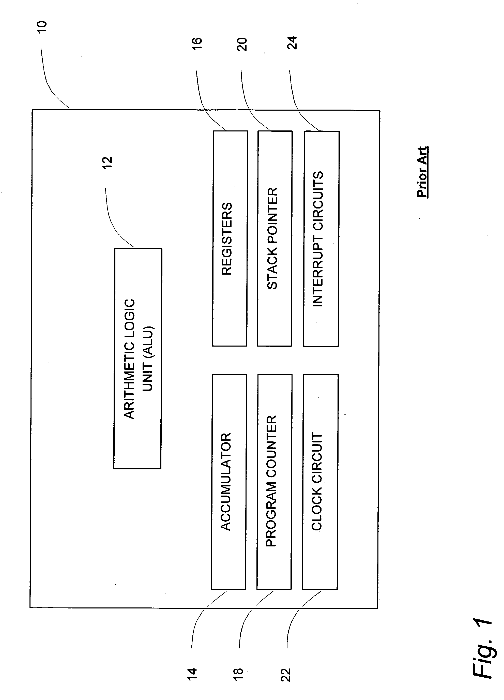
Because of the complexity of the calculations that the microprocessor performs, the programs that control its operation are generally relatively large, requiring the use of mass storage devices to house them.
Disjunctive Normal Form

Method used


Image

  • Enhanced boolean processor
  • Enhanced boolean processor
  • Enhanced boolean processor

Examples


example 2

[0163] If Dev7=22 goto 200

[0164] Else goto 100

2 Micro-code Value of Sequence # Instruction Register Operation 1 00000111 00010110 001 OR 2 00000000 00000000 000 AND 3 00000000 11001000 101 Conditional Jump 4 00000000 01100100 100 Unconditional Jump

[0165] As illustrated in FIG. 4, the next operation address register 42 and the end of OR address register 44 may be loaded with values from the n-bit "address" portion of the instruction register 40. As described previously, these values specify the addresses of lines of code within the micro-program that are jumped to when performing short circuit operations. However, this design limits the number of micro-program lines (or micro-program addresses) that can be accessed by the next operation address register 42 and the end of OR address register 44 to 2.sup.n, where n is the width, in bits, of the address portion of the instruction register 40.

[0166] In order to expand the micro-program address values that can be stored in the next operat...

example 3

[0180] If (Dev1=8 and Dev2=0) or (Dev3=10 and Dev2=0) then Dev9=20

3 Micro-code Value of Sequence # Instruction Register Operation 1 00000001 00001000 001 AND 2 00000010 00000000 001 AND 3 00000000 00000000 000 OR 4 00000011 00001010 001 AND 5 00000010 00000000 001 AND 6 00001001 00010100 010 End of Operation

example 4

[0181] If Dev7=22 goto 200

[0182] Else goto 100

4 Micro-code Value of Sequence # Instruction Register Operation 1 00000111 00010110 001 AND 2 00000000 00000000 000 OR 3 00000000 11001000 101 Conditional Jump 4 00000000 01100100 100 Unconditional Jump

[0183] Once again, as illustrated in FIG. 5, the end of operation address register 142 and the end of AND address register 144 may be loaded with values from the n-bit "address" portion of the instruction register 140. However, in order to expand the micro-program address values that can be stored in the end of operation address register 142 and the end of AND address register 144, the architecture may be modified to use the bits from both the address and control / state portions of the instruction register 140 when loading the end of operation address register 142 and the end of AND address register 144 with the values of micro-program addresses. This approach would require the "control / state" portion of the instruction register 140 to be c...


PUM


Abstract

A set of processors, co-processors and processor cores having a Boolean logic unit, wherein the Boolean logic unit is operable, respectively, for performing the short-circuit evaluation of Conjunctive Normal Form Boolean expressions/operations, Disjunctive Normal Form Boolean expression/operations, or both. Each processor or processor core also includes a plurality of input/output interfaces, operable for receiving a plurality of compiled Boolean expressions/operations and transmitting a plurality of compiled results, and a plurality of registers. An associated processing method including starting an operation related to a Conjunctive Normal Form Boolean expression comprising a conjunct or related to a Disjunctive Normal Form Boolean expression comprising a disjunct, evaluating the conjunct or disjunct, and selectively short-circuiting a portion of the Boolean expression.

Description

[0001] This application is a continuation-in-part of U.S. patent application Ser. No. 10 / 075,917 filed Feb. 13, 2003, which claims the benefit of provisional U.S. Patent Application Serial No. 60 / 268,471 filed Feb. 14, 2001; provisional U.S. Patent Application Serial No. 60 / 268,472 filed Feb. 14, 2001; and provisional U.S. Patent Application Serial No. 60 / 268,478 filed Feb. 14, 2001.[0002] In addition, this application is entitled to the benefit of, and claims priority to, provisional U.S. Patent Application Serial No. 60 / 454,684 filed Mar. 17, 2003 and entitled "BOOLEAN CO-PROCESSOR;" provisional U.S. Patent Application Serial No. 60 / 479,586 filed Jun. 19, 2003 and entitled "BOOLEAN PROCESSING MEMORY & DEVICE SYNCHRONIZATION;" provisional U.S. Patent Application Serial No. 60 / 483,061 filed Jun. 30, 2003 and entitled "BOOLEAN PROCESSOR EXPANDED SHORT-CIRCUIT ADDRESSING;" provisional U.S. Patent Application Serial No. 60 / 495,822 filed Aug. 18, 2003 and entitled "BOOLEAN PROCESSOR INT...

Claims


Application Information

Patent Timeline
IPC IPC(8): G06F9/308
CPCG06F9/3879G06F9/30018
Inventor KOCH, KENNETH E. III
Owner JUNIVERSITI OF NORT KAROLINA EHT SHARLOTT
Why Eureka
Try Eureka