Blood flow monitor with venous and arterial sensors

a blood flow monitor and sensor technology, applied in the field of blood flow monitors with venous and arterial sensors, can solve problems such as thermal fluctuations inherent in the bloodstream, and achieve the effect of low thermal energy level

Inactive Publication Date: 2004-09-16
THERMAL TECH
View PDF5 Cites 11 Cited by
  • Summary
  • Abstract
  • Description
  • Claims
  • Application Information

AI Technical Summary

Benefits of technology

0010] Thus, in the preferred embodiment of the invention the temperature difference over at least one respiratory cycle is measured and averaged to provide an average temperature difference. The averaging, or integrating, action effectively eliminates, as a confounding factor in the determination of cardiac output, the effect of instantaneous blood temperature fluctuations, such as cyclical, respiratory-induced fluctuations.
0011] To make such determinations, an average temperature difference is first calculated over a time period of at least one respiratory cycle in which no thermal energy is introduced into the blood flow path. Thermal energy of a predetermined and relatively low magnitude is then introduced into the blood flow path to produce a heating action therein at a location between the two temperature sensors. Once the temperature rise induced by the heating stabilizes, the average temperature difference between the two locations is again calculated from temperature difference measurements over a time period of at least one respiratory cycle at the higher temperature level. The difference between the average temperature differences which occurs when the thermal energy is turned on, referred to as the rising temperature change, is determined. The difference between the average temperature differences which occurs when the thermal energy is turned off, referred to as the falling temperature change, is similarly determined. The cardiac output is calculated as a function of the thermal energy input and the rising and falling temperature changes. Because a relatively low level of thermal energy is used in making measurements, the overall sequence of determinations can be safely repeated multiple times per minute, for example, so that an effectively continuous, or quasi-continuous, determination of cardiac output is obtained.

Problems solved by technology

A principal limitation in the quantification of cardiac output is the existence of thermal fluctuations inherent in the bloodstream.

Method used


Image

  • Blood flow monitor with venous and arterial sensors
  • Blood flow monitor with venous and arterial sensors
  • Blood flow monitor with venous and arterial sensors

Examples


Embodiment Construction

[0015] The invention is described in detail with the help of the accompanying drawings wherein:

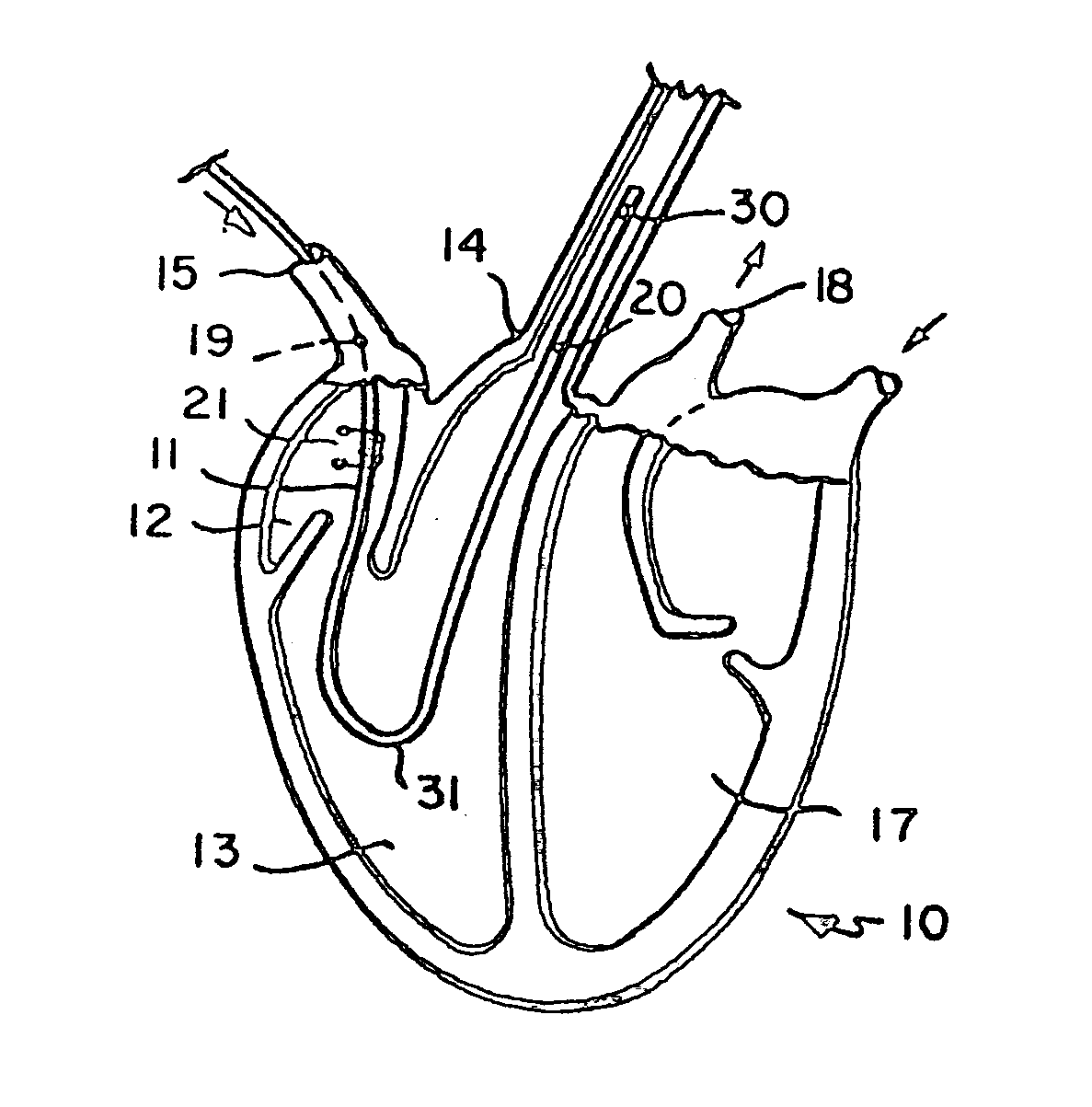
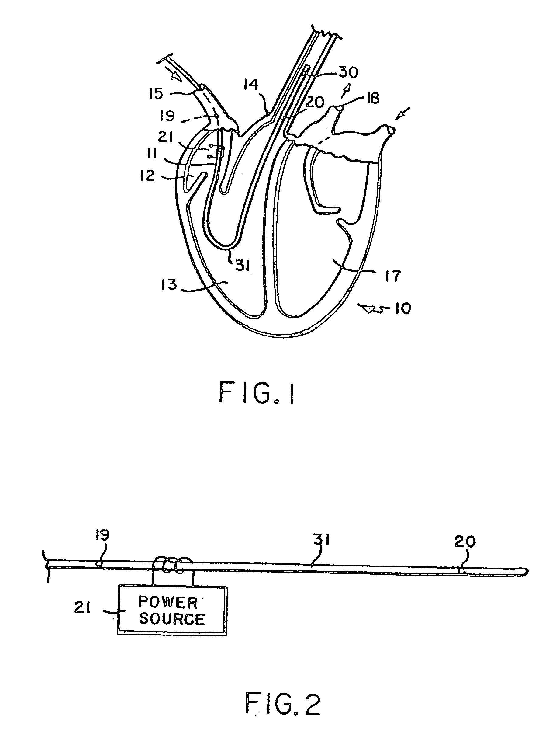
[0016] FIG. 1 shows a simplified diagrammatic view of a human heart;

[0017] FIG. 2 shows a simplified diagrammatic view of a catheter useful in the invention;

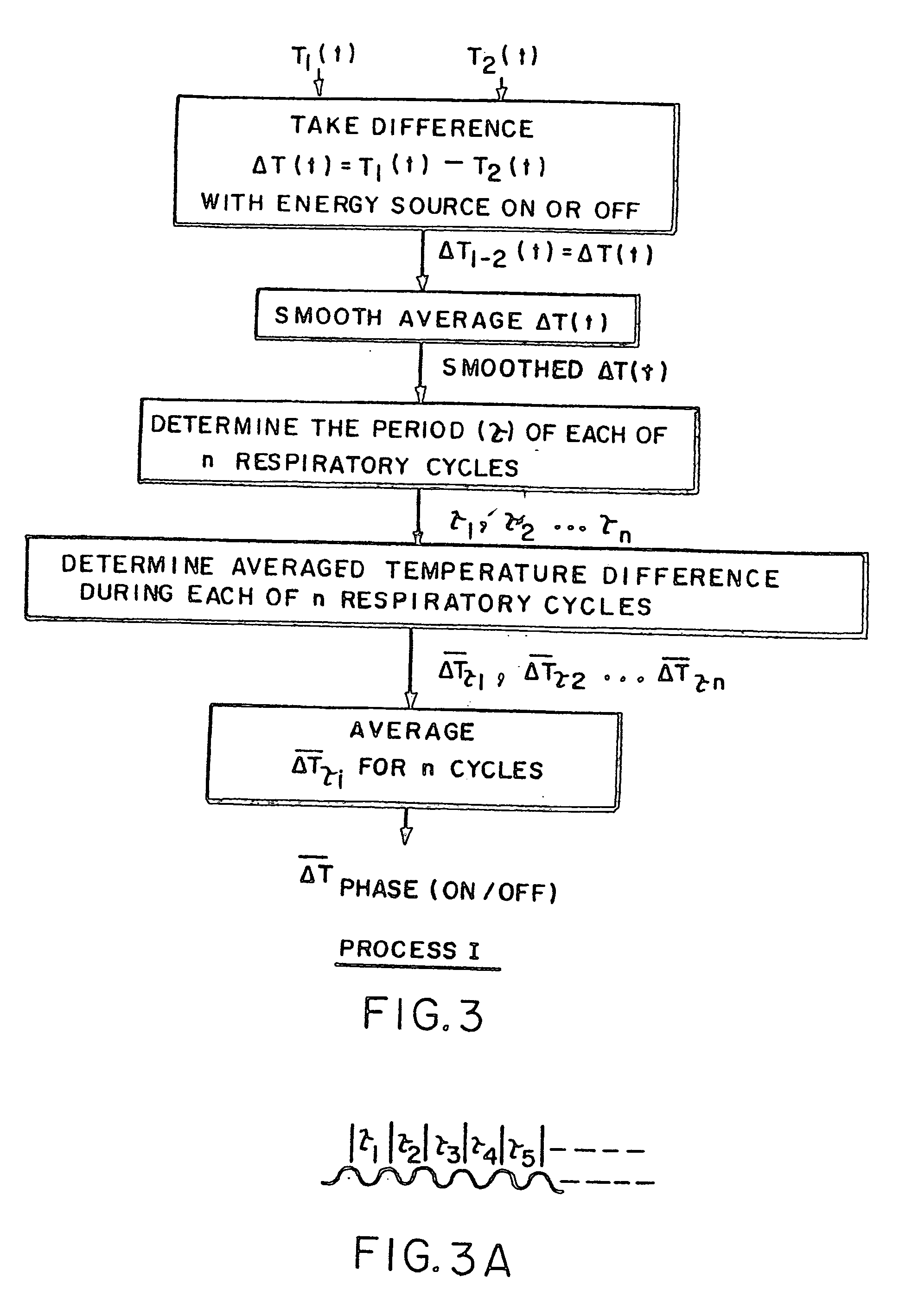
[0018] FIG. 3 shows a flow chart depicting steps in a process used in the invention;

[0019] FIG. 3A shows a smooth temperature difference curve obtained in the process depicted in FIG. 3;

[0020] FIG. 4 shows a flow chart depicting further steps in a process used in the invention;

[0021] FIG. 5 shows a flow chart depicting still further steps in a process of the invention;

[0022] FIG. 6 shows a graph depicting a temperature / time relation used in the invention;

[0023] FIG. 7A shows a simplified diagrammatic view of another catheter used in the invention;

[0024] FIG. 7B shows a flow chart depicting steps in still another process of the invention;

[0025] FIGS. 8A, 8B and 8C show flow charts depicting modes of operating the process of the inventio...


PUM


Abstract

A technique is disclosed for determining blood flow in a living body by changing the thermal energy level in the venous blood flow path and determining temperatures in both the venous and arterial blood flow paths. Blood flow is calculated as a function of the change in energy level and the temperature differences in the venous and arterial blood flow paths.

Description

PRIORITY CLAIM[0001] This application claims priority from commonly owned copending U.S. Provisional Application Serial No. 60 / 458,100, filed Mar. 26, 2003, and commonly owned copending Nonprovisional U.S. application Ser. No. 10 / 364,773, filed Feb. 11, 2003.[0002] This invention relates generally to techniques for measuring blood flow in a body and, more particularly, to the use preferably of one or more temperature sensors for measuring thermal energy changes in the blood flowing through the heart and to the use of unique data processing techniques in response thereto for determining cardiac output.[0003] While the invention can be used generally to measure blood flow at various locations in a body, it is particularly useful in measuring blood flow in the heart so as to permit the measurement of cardiac output. Many techniques for measuring cardiac output have been suggested in the art. Exemplary thermodilution techniques described in the technical and patent literature include: "...

Claims


Application Information

Patent Timeline
Patent Type & Authority Applications(United States)
IPC IPC(8): A61B5/028
CPCA61B5/029A61B5/028
Inventor BOWMAN, HARRY FREDERICK
Owner THERMAL TECH
Why Eureka
Try Eureka