Vehicle axle and method and apparatus for manufacturing the same

a technology of axles and axles, applied in the direction of shafts, laser beam welding apparatus, welding/soldering/cutting articles, etc., can solve the problems of achieve the effects of rational manufacture, high strength, and limited thermal effects on surrounding materials

Inactive Publication Date: 2004-09-23
FERRUFORM
View PDF4 Cites 14 Cited by
  • Summary
  • Abstract
  • Description
  • Claims
  • Application Information

AI Technical Summary

Benefits of technology

0007] Another object of the invention is to enable rational manufacture of vehicle shafts of the type indicated in the preamble to claim 1. To this end, the invention is distinguished by what is indicated in the characterising part of claim 1. The shaft ends and the shaft journals having the same material thickness and being machined to cooperating planes makes it possible in the process according to the invention for laser welding at reasonable powers and feed rates to be used, thereby making rational manufacture possible. At the same time, the welding beam may be given a focus which creates the possibility of a weld seam which goes through even relatively thick material and satisfies the requirement for high strength. By limiting the extent of the welding beam and hence of the weld seam, the thermal effects on surrounding material can be limited. A relatively moderate clamping force will hold the workpieces fixed in position and there will be no need for direction correction measures after the welding. It will nevertheless be possible for the shaft journals and the intermediate shaft portion to be within the predetermined dimensional tolerances.
0008] The shaft journals and the shaft portion are made of steel material and the mutually abutting end surfaces are preheated in a reg

Problems solved by technology

By limiting the extent of the welding beam and hence of the weld

Method used


Image

  • Vehicle axle and method and apparatus for manufacturing the same
  • Vehicle axle and method and apparatus for manufacturing the same
  • Vehicle axle and method and apparatus for manufacturing the same

Examples


Embodiment Construction

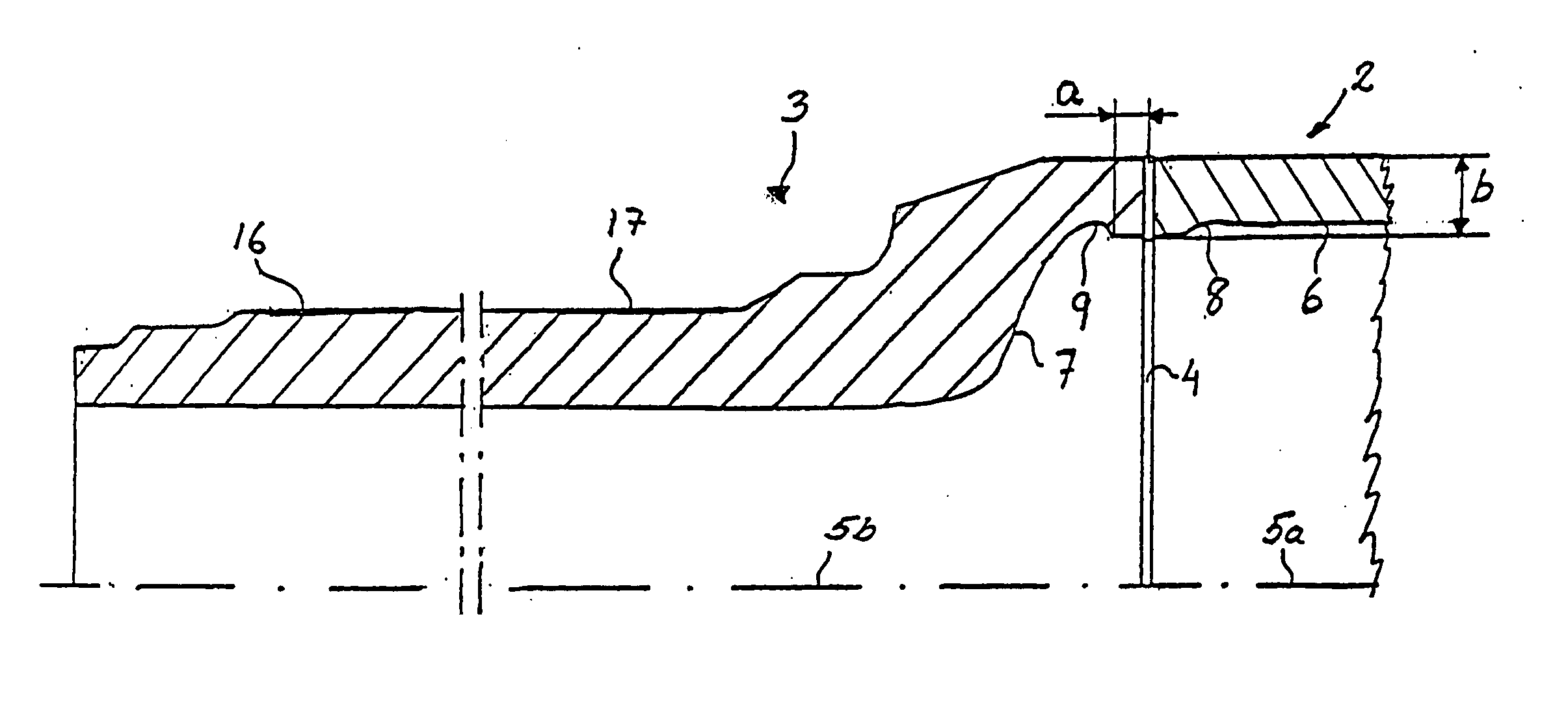
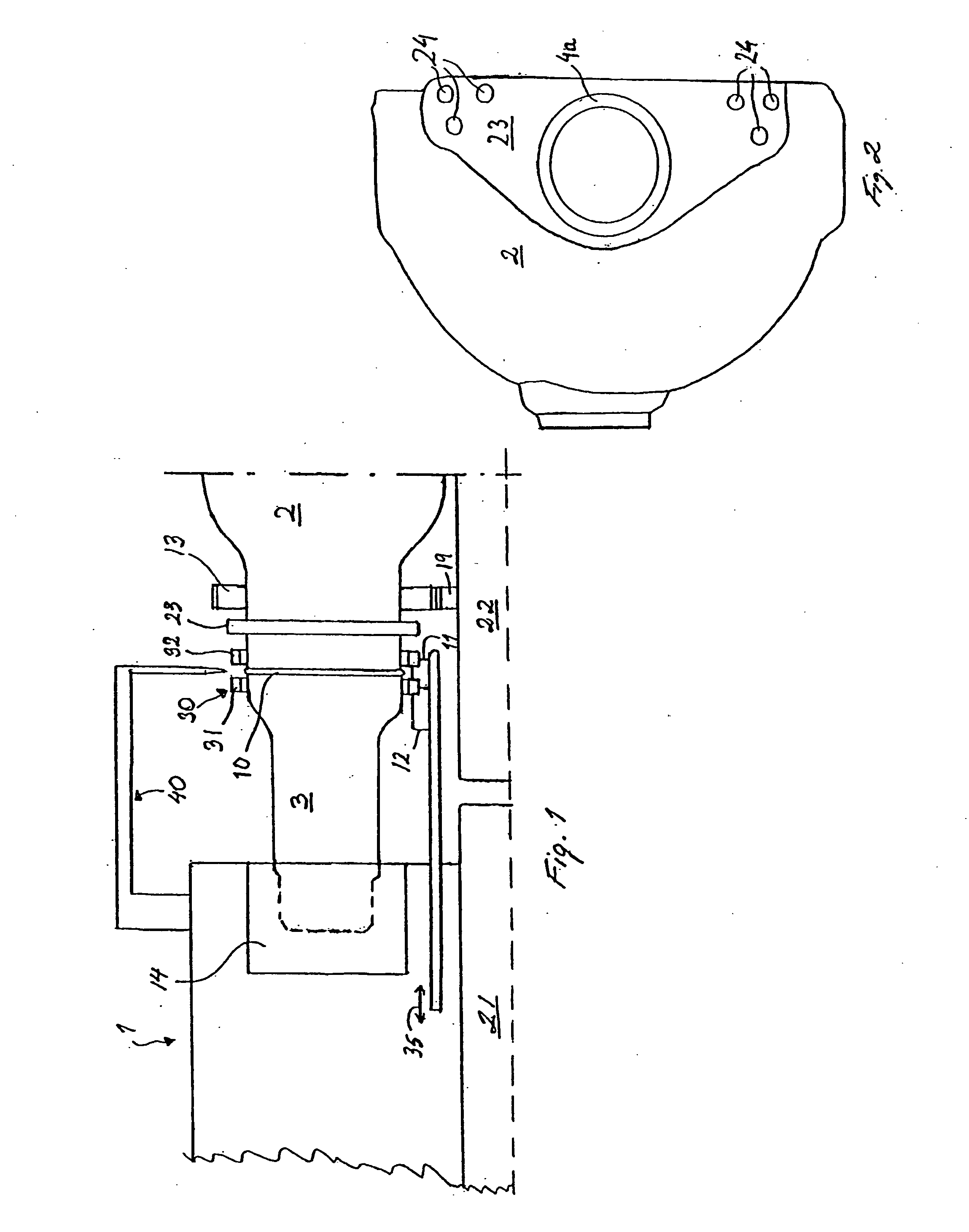
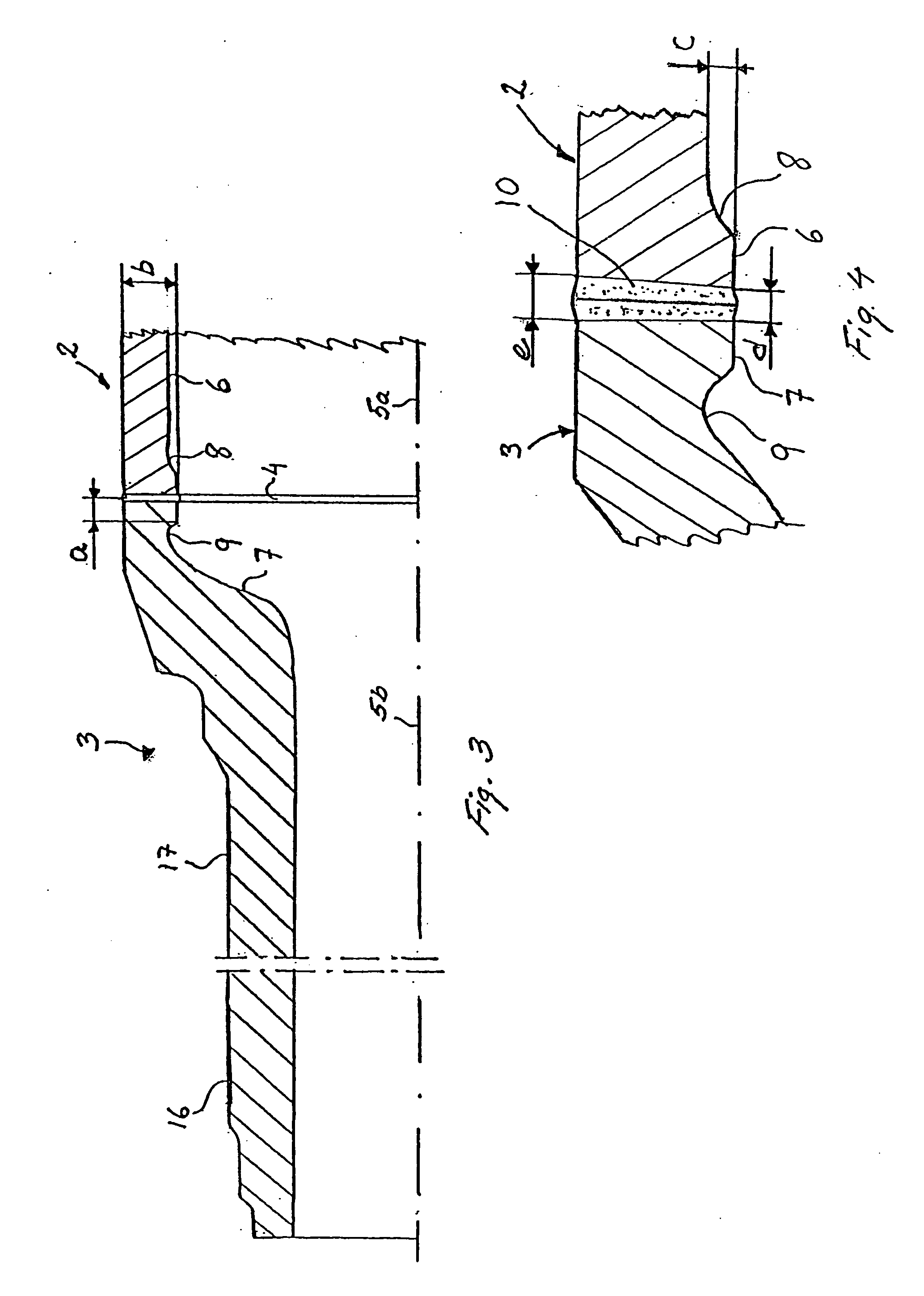
[0016] FIG. 1 depicts a machine-tool 1 (hereinafter also called the welding machine) in which an intermediate shaft portion 2 and a shaft journal 3 which is connectable to the latter are clamped. Said shaft portion takes the form here of a usual type of heavy vehicle rear axle beam, only one half of which appears in the diagram. It is to be understood that the rear axle beam has the corresponding other half clamped in a corresponding other half of the machine 1.

[0017] FIG. 2 shows the shaft portion 2 having at each of its respective ends a terminal surface 4a which is annular--with advantage, circular--and which symmetrically surrounds a central axis 5a which is substantially perpendicular to the terminal surface 4a (see FIGS. 2 and 3). A brake bracket 23 is also welded to the rear axle beam 2 to support braking equipment (not depicted) fastened to the vehicle shaft by undepicted threaded connections in holes 24. It is to be understood that the respective journals 3 each exhibit a c...


PUM

PropertyMeasurementUnit
Lengthaaaaaaaaaa
Lengthaaaaaaaaaa
Lengthaaaaaaaaaa

Abstract

A vehicle shaft has a rigid intermediate portion with a shaft journal welded to each of the two ends of the shaft portion. The shaft journal and/or the intermediate portion are/is provided with a material thickness reduction within a distance a from the contact surfaces which is less than substantially half the material thickness at the contact surfaces, in order to guide the force flow thorough the weld seam. During manufacture of such vehicle shafts, the mutually abutting contact surfaces are laser-welded to form a weld seam which can fully penetrate the material of the shaft journals and the intermediate portion respectively, whereby the concentricity and parallelism of the two journals will be within predetermined dimensional tolerances after the welding and cooling of the material. The arrangement has an induction heater which surrounds the shaft journal and is movable axially so that, after completion of heating, it moves to free the shaft journals welded to the shaft portion.

Description

[0001] The present invention relates to a vehicle shaft according to the preamble to claim 1, and a process for manufacturing a vehicle shaft and an arrangement for implementing that process in accordance with the preambles to claims 4 and 9 respectively.STATE OF THE ART[0002] A vehicle shaft in the form of an intermediate shaft portion with welded-on shaft journals and a method for manufacturing such a shaft are already known from American patent specification 4048466. In that case the axial ends of the shaft journals, as also the axial ends of the rear axle beam which cooperate with them, are provided with a special shoulder intended to maintain a correct position of the journals relative to the rear axle beam during welding. That method entails the whole of the shaft journals being finish-machined before being welded to a rear axle beam by electron beam welding.[0003] Also, a practice known from European patent specification EP 1 053 822 in the laser welding of a gearwheel to a s...

Claims


Application Information

Patent Timeline
IPC IPC(8): B23K26/00B60B35/16B23K26/20B23K26/28B23K103/04B60B35/00
CPCB23K26/285B60B35/166B60B2310/208B60B2310/228Y10T29/49968B60B2360/102B60B2900/113B60Y2200/14Y10T29/49826B60B2310/3026B23K26/282
Inventor GUSTAFSSON, BERTILENGSTROM, HANSNILSSON, KLAS
Owner FERRUFORM
Why Eureka
Try Eureka