
Apparatus for mixing and dispensing components

a technology applied in the field of apparatus for mixing and dispensing components, can solve the problems of limiting activity, reducing life quality, and reducing the risk of vertebral fracture surgery, and achieve the effect of limiting exposur

Inactive Publication Date: 2004-10-07
GLOBUS MEDICAL INC
View PDF10 Cites 95 Cited by
  • Summary
  • Abstract
  • Description
  • Claims
  • Application Information

AI Technical Summary

Benefits of technology

[0014] The invention relates to apparatus, kits, and methods for mixing and dispensing components. The methods and apparatus of the invention can be adapted to mix and dispense any components but are particularly useful where the components require isolation from the surrounding atmosphere, for example, in cases where the components are adversely affected by air or because the components give off toxic vapors. The methods and apparatus of the invention are particularly appropriate where controlled and consistent mixing and dispensing are desired as well as limiting the exposure of those in proximity to any noxious fumes generated during the mixing process.
[0020] The sealed mixing chamber controllably communicates with the dispensing chamber by a controllable portal. In the mixing phase, the controllable portal is closed. After mixing is complete, the controllable portal is opened creating a flow path whereby the dispensing chamber receives the bone cement. The dispensing chamber comprises a dispensing portal, preferably, adapted to connect to a flexible tube, high-pressure hose, cannula, or a standard needle to deliver the mixed bone cement to a patient's vertebra. The dispensing chamber also communicates with a drive mechanism for forcing the bone cement through the dispensing portal and into the vertebroplasty delivery tube. In preferred embodiment, a single drive connection is used to mix the components and to dispense the components thereby reducing the number of manipulations required for mixing and dispensing bone cement.

Problems solved by technology

The pain and loss of movement accompanying vertebral fractures severely limits activity and reduces the quality of life.
In contrast to typical bone fractures, the use of surgery to treat vertebral fractures is extremely difficult and risky.
There are serious control problems with current cannula-type bone-cement dispensation systems.
While the procedure itself has proven very effective, problems are associated with handling and mixing the bone cement.
Removal of the mixed cement from the mixing vessel into the caulking gun or syringe is cumbersome, time consuming, and has the potential for being mishandled, dropped or contaminated.
The increased pressure requirement makes control difficult and increases the likelihood that too much cement will be injected.
For example, when the x-ray indicates that the vertebrae is filled, it is difficult to stop the cement flow out of the cannula and overflow of the cement into the surrounding tissues can result.
This is unsafe for the patient since the excess cement may leak out of the vertebral body into surrounding tissue and vascular structures.
Another disadvantage with current bone cement mixing protocols that require open-air transfers stems from the toxic nature of the liquid monomer component.
Bone cement monomers, including methyl methacrylate, give off toxic vapor and are irritating to the eyes and respiratory system.
Furthermore, acrylate monomer irritates skin and contact with minute concentrations can cause sensitization.
Unfortunately, this method risks injury to operating-room personnel from broken glass or sharp edges.
Another disadvantage is that small glass shards often form during such breaking, which can fall into the cement mixture.
In attempting to satisfy this requirement, substantial construction and operational difficulties have occurred with these prior art systems.
Furthermore, in other prior art systems, manual addition of the monomer is required, exposing the user to the foul odor of the monomer and the substantial difficulties typically encountered in handling such products.

Method used


Image

  • Apparatus for mixing and dispensing components
  • Apparatus for mixing and dispensing components
  • Apparatus for mixing and dispensing components

Examples


Embodiment Construction

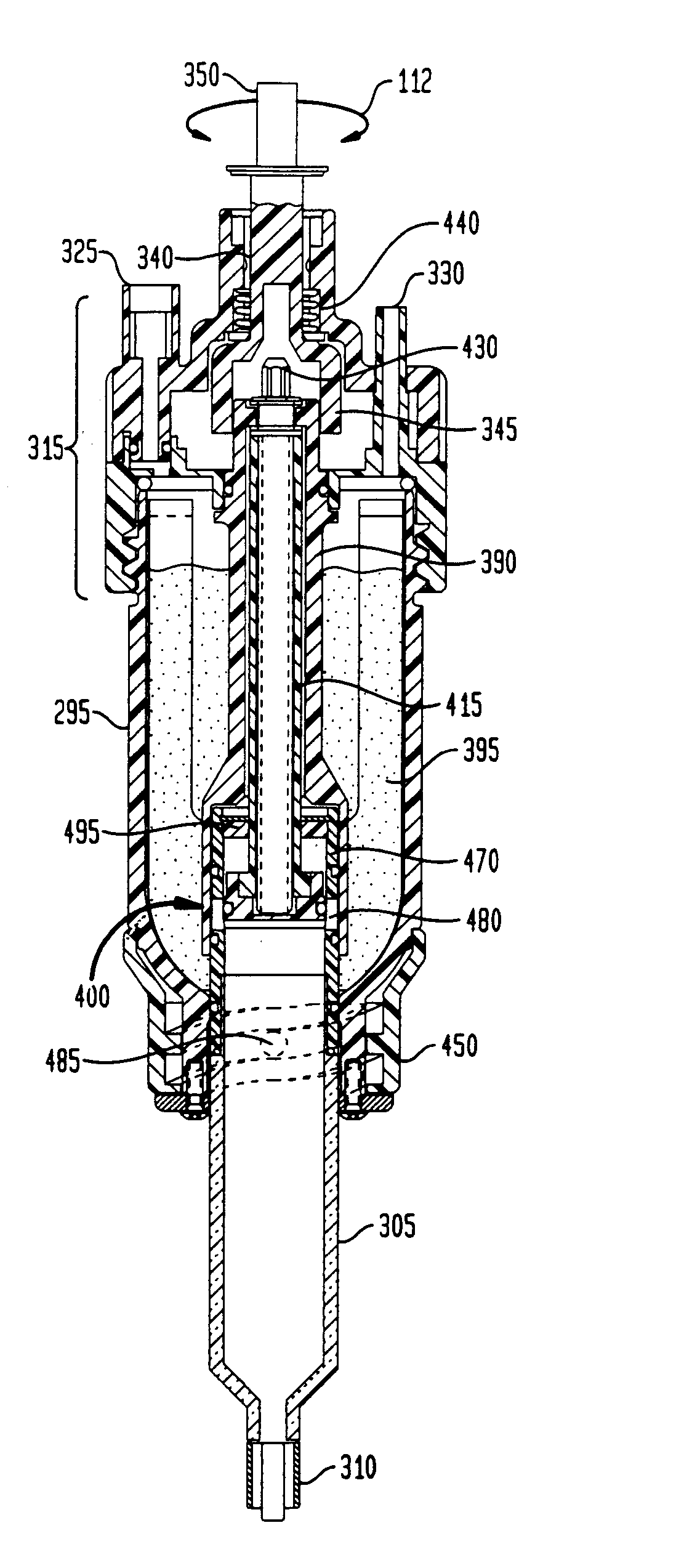
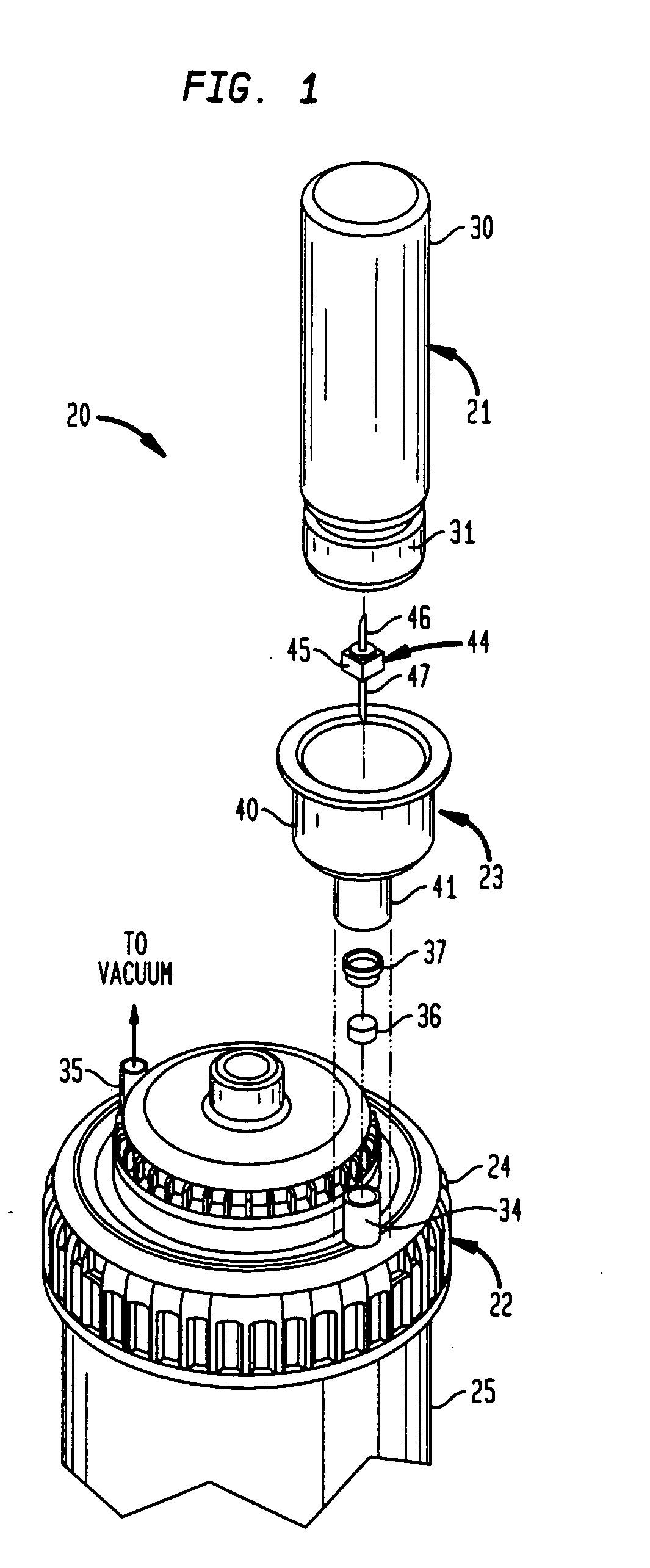
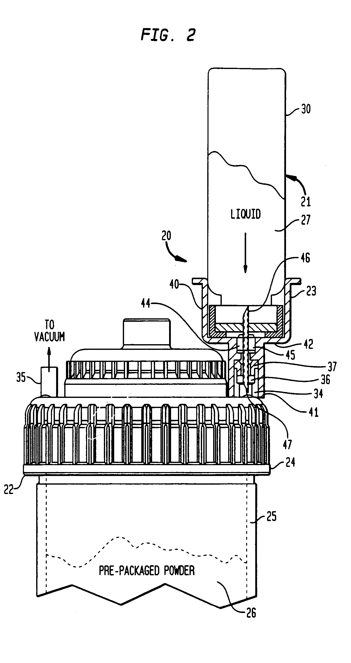
[0042] By referring to FIGS. 1-11, along with the following detailed discussion, the construction and operation of the preferred multi-component product handling and delivering systems of the present invention can best be understood. However, as will become evident from this disclosure, further alternate embodiments of the present invention can be implemented without departing from the scope of the present invention. Consequently, the embodiments detailed in FIGS. 1-11, and in the following detailed disclosure, are intended for exemplary purposes, and not as a limitation of the present invention.

[0043] The present invention can be employed with any type of vessel used to intermix the two or more components. Thus, the present invention is not limited to combining or mixing bone cements.

[0044] The components of the multi-component product handling and delivering systems of the present invention can be packaged and sold together as a kit.

[0045] In FIGS. 1, 2, 6, and 7, multi-component ...


PUM


Abstract

Apparatus and methods for mixing and dispensing components. The methods and apparatus of the invention are particularly advantageous to manually mix the components of radiopaque bone cement and inject the resulting radiopaque bone cement into skeletal structures. The manually actuated apparatus of the invention comprises: (1) a sealed mixing chamber for mixing components; (2) a dispensing chamber isolated from the sealed mixing chamber; (3) a controllable portal to open a flow path between the sealed mixing chamber and the dispensing chamber so that the dispensing chamber can receive the mixed components after they are mixed; and (4) a drive mechanism associated with the dispensing chamber to force the mixed contents from the dispensing chamber.

Description

1. CROSS REFERENCE TO RELATED APPLICATIONS[0001] This application is a continuation-in-part of U.S. patent application Ser. No. 10 / 438,471 filed by D. Barker et al. on May 15, 2003, and entitled "Apparatus For Mixing And Dispensing Components". The parent Ser. No. 10 / 438,471 application is incorporated herein by reference.[0002] The parent application is also a continuation-in-part of application Ser. No. 10 / 266,053, filed on Oct. 7, 2002, entitled Multi-Component, Product Handling And Delivery System, by J. Seaton et al., which application is hereby incorporated herein by reference.[0003] This application is a continuation-in-part of application Ser. No. 10 / 417,553, filed on Apr. 17, 2002, entitled Multi-Component Handling And Delivery System, by J. Seaton et al., which application is hereby incorporated herein by reference.[0004] This application also claims the benefit of U.S. Provisional Application No. 60 / 424,398 filed on Nov. 6, 2002, entitled Multi-Component, Product Handling...

Claims


Application Information

Patent Timeline
Patent Type & Authority Applications(United States)
IPC IPC(8): B01F27/75A61B19/02A61F2/00A61F2/46
CPCA61B17/8833A61B2017/8838A61B2019/0218A61F2002/30561A61F2002/4685A61F2250/0071B01F7/00408B01F13/002B01F13/0033B01F13/06B01F15/00435B01F15/00506B01F15/0205B01F15/0206B01F15/0212B01F15/0216B01F15/0225B01F15/0237B01F15/0258B01F15/0267B01F15/027B01F15/0278B01F15/0279B01F2215/0029A61B2050/0064B01F27/1142B01F33/5011B01F33/5014B01F33/70B01F35/3202B01F35/713B01F35/7131B01F35/7137B01F35/714B01F35/7163B01F35/7174B01F35/718B01F35/752B01F35/751B01F35/75425B01F35/754251B01F2101/20B01F35/32
Inventor BARKER, DONALDBOGERT, ROY B.CARR, JOHN P.NELSON, JAMES W.TREBING, LINDA M.GLEASON, KENNETH R.BIANCHI, DAMIAN
Owner GLOBUS MEDICAL INC
Learn More