High loft low density nonwoven webs of crimped filaments and methods of making same

a technology of crimped filament and nonwoven webs, which is applied in the field of high loft low density nonwoven webs of crimped filament and methods of making same, and achieves the effects of high loft, greater open space and high lo

Inactive Publication Date: 2004-10-07
KIMBERLY-CLARK WORLDWIDE INC
View PDF58 Cites 26 Cited by
  • Summary
  • Abstract
  • Description
  • Claims
  • Application Information

AI Technical Summary

Benefits of technology

[0039] Words of degree, such as "about", "substantially", and the like are used herein in the sense of "at, or nearly at, when given the manufacturing, design, material and testing tolerances inherent in the stated circumstances" and are used to prevent the unscrupulous infringer from unfairly taking advantage of the invention disclosure where exact or absolute figures are stated as an aid to understanding the invention.
[0040] As used herein, the term "machine direction" or MD means the length of a fabric in the direction in which it is produced. The term "cross machine direction" or CD means the width of fabric, i.e. a direction generally perpendicular to the MD.
[0041] "Particle," "particles," "particulate," "particulates" and the like, refer to a I) material that is generally in the form of discrete units. The particles can include granules, pulverulents, powders or spheres. Thus, the particles can have any desired shape such as, for example, cubic, rod-like, polyhedral, spherical or semi-spherical, rounded or semi-rounded, angular, irregular, etc. Shapes having a large greatest dimension / smallest dimension ratio, like needles, flakes and fibers, are also contemplated for use herein. The use of "particle" or "particulate" may also describe an agglomeration including more than one particle, particulate or the like.
[0042] "Shingled," "shingling," or a "shingled layer," refers to an effect wherein a nonwoven web may be layered on itself owing to the overlap of fiber deposition on the forming surface as the jet of fibers coming from the die head oscillates back and forth over the moving collection wire resulting in the laying down of overlapping rows in the manner of shingles. Z-direction buckling may occur where the oscillations of fiber collection result in a Z-direction accumulation of the fibers which then fall towards the X-Y plane of the web resulting in the described shingling. The shingling and buckling thereof may be substantially irregular or random in nature but provide a higher loft and greater open space within the web.DESCRIPTION OF PREFERRED EMBODIMENTS
[0043] FIG. 1 is a schematic diagram illustrating methods and apparatus of this invention for producing high loft, low density materials by producing crimpable bicomponent side by side substantially continuous fibers and causing them to crimp in an unrestrained environment.
[0044] Referring to FIG. 1, a schematic diagram is shown illustrating exemplary methods and apparatus of this invention for producing high loft, low density materials by producing crimpable bicomponent side by side substantially continuous fibers and causing them to crimp in an unrestrained environment. Two polymers A and B are spun with known thermoplastic fiber spinning apparatus 21 to form bicomponent side by side, or A / B, polymer masses 23. The polymer masses 23 are then traversed through a fiber draw unit (FDU) 25 to form fibers 24. According to one embodiment of the present invention, unlike the standard practice in the art, the FDU is not heated, but is left at ambient temperature (e.g., 65.degree. F.). Thus, while the polymers will be recognized as having been heated to extrude the polymer masses, the actual fibers, as formed in the ambient temperature FDU, will be referred to and understood herein as having been deposited onto a forming surface without the addition of heat to the fibers before deposition. The fibers 24 are left in a substantially continuous state and are deposited on a moving forming wire or surface 27. Deposition of the fibers 24 is aided by an under-wire vacuum supplied by a negative air pressure unit, or below wire exhaust, 29.

Problems solved by technology

However, in such constructions the fibers of the web still remain in the plane of the web, it is only the plane of the web itself which has been distorted.

Method used


Image

  • High loft low density nonwoven webs of crimped filaments and methods of making same
  • High loft low density nonwoven webs of crimped filaments and methods of making same
  • High loft low density nonwoven webs of crimped filaments and methods of making same

Examples


example 1

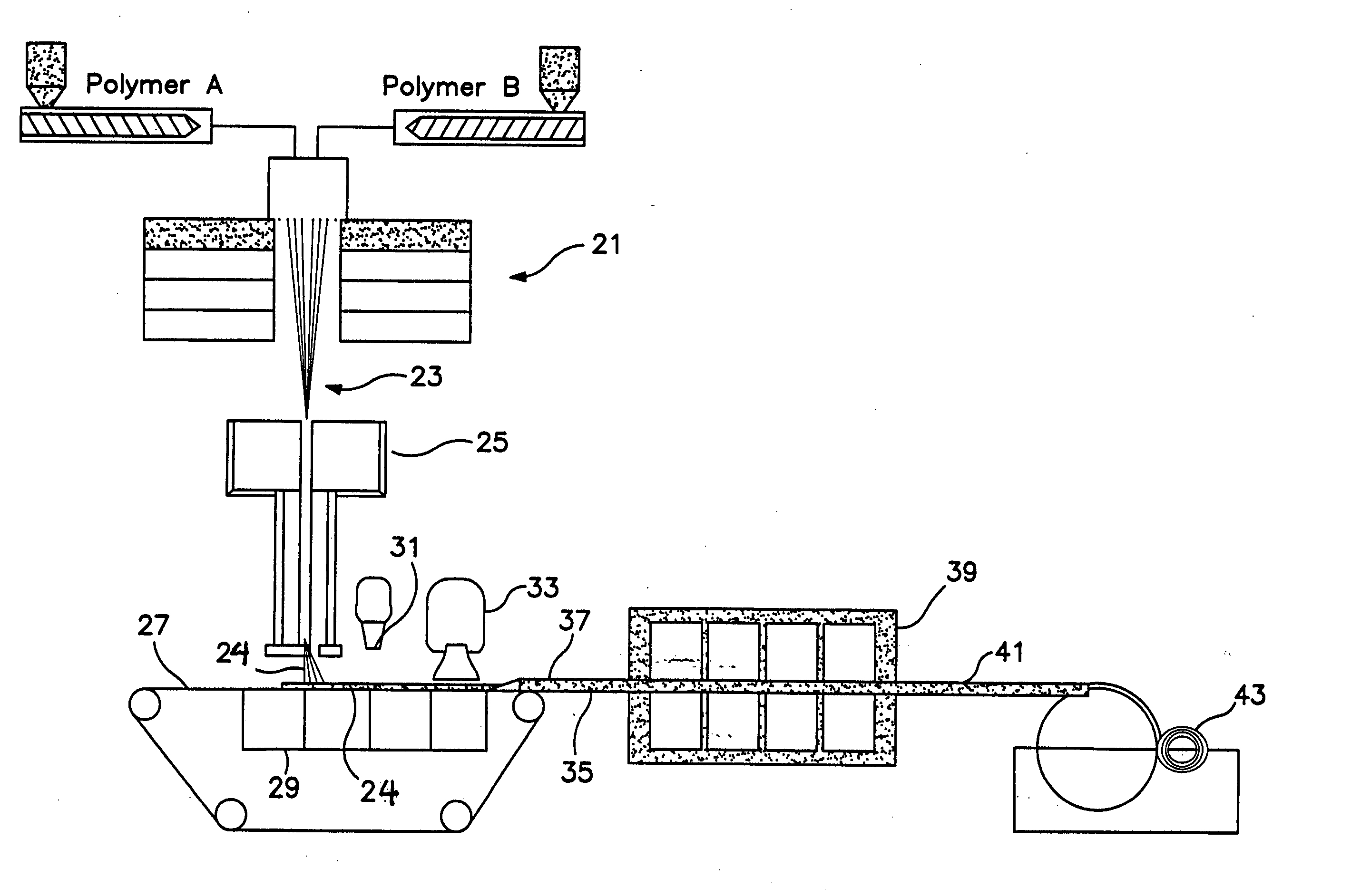
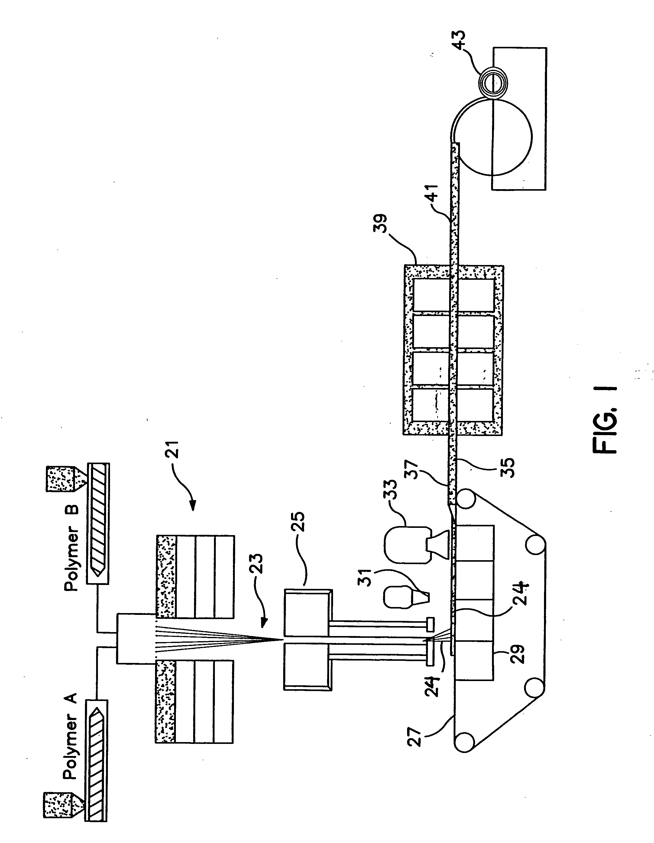
[0094] Example 1, was produced according to the present invention to a basis weight of 202 gsm (5.96 osy), with a bulk of 12.6 mm (0.5 inch) and density of 0.016 g / cc. The average denier was measured to be approximately 3.3 dpf (denier per fiber). The fibers were side by side bicomponent, featuring polymer A of Dow 61800.41 polyethylene (PE) and polymer B of Exxon 3155 polypropylene (PP). A TiO.sub.2 additive from the Standridge Color Corporation, of Social Circle, Ga., tradenamed SCC-4837, was added to the polymer prior to extrusion at 2% by weight to provide white color and opacity to the web. The fibers were spun through a 96 hole per inch (hpi) spinpack, spinning in an A / B side by side (s / s) configuration, at a melt temperature of 410.degree. F.

[0095] Throughput was balanced in a 50 / 50 throughput ratio between the two polymers, with a total throughput of 0.7 grams per hole per minute (ghm). The quench air temperature was 55.degree. F. The fiber spin length was 48 inches. The fib...

example 2

[0097] Example 2, was produced according to the present invention to a basis weight of 79 gsm (2.33 osy), with a bulk of 3.8 mm (0.15 inches) and density of 0.021 g / cc. The average denier was measured to be approximately 3.3 dpf. Polymers and additives were the same as stated for Example 1.

[0098] Fiber and web formation conditions were the same as for Example 1 except the forming wire was moving at 220 ft / min, as measured on the forming wire. The HAK was set at 250.degree. F. and 5.0 inches H.sub.2O of pressure on bank 1, and 240.degree. F. and 3.5 inches H.sub.2O on bank 2, at a height of 5.0 inches above the forming wire. The below wire exhaust under the fiber draw unit was set to vacuum of approximately 1.7 inches H.sub.2O in bank 1, and 3.8 inches H.sub.2O in bank 2.

example 3

[0099] Example 3, was produced according to the present invention to a basis weight of 77 gsm (2.27 osy), with a bulk of 3.3 mm (0.13 inch) and density of 0.023 g / cc. The average denier was measured to be approximately 3.3 dpf.

[0100] Fiber and web formation conditions were the same as for Example 1 except the forming wire was moving at 229 ft / min, as measured on the forming wire. The RAK was set at 250.degree. F. and 5.0 inches H.sub.2O of pressure on bank 1, and 240.degree. F. and 3.5 inches H.sub.2O on bank 2, at a height of 5.0 inches above the forming wire. The below wire exhaust under the fiber draw unit was set to vacuum of approximately 1.6 inches H.sub.2O in bank 1, and 3.8 inches H.sub.2O in bank 2. The web was bonded at approximately 262-269.degree. F. in a through air bonder.


PUM

PropertyMeasurementUnit
densitiesaaaaaaaaaa
densityaaaaaaaaaa
diameteraaaaaaaaaa

Abstract

High loft, low density nonwoven webs of increased uniformity are produced by forming substantially continuous, spunbond, crimped, bicomponent fibers of A / B side by side morphology in an unheated fiber draw unit. The fibers are then heated and cooled in the absence of impeding forces to achieve maximum crimp in the z-direction and produce a web of lofted material. The resultant material is particularly suitable for use as an insulator. Particulates may be added to the webs if desired.

Description

[0001] This application is a Continuation In Part application and claims priority from U.S. application Ser. No. 10 / 037,467, filed 21 Dec. 2001.[0002] This invention relates to a high loft, low density nonwoven material produced from continuous fibers in which the lofty character of the nonwoven material is the result of the fibers comprising the web having a Z-direction orientation, resulting from improved processing and the resultant crimping. These materials have increased uniformity and are particularly suitable for use in a broad range of applications including, without limitation, surge layers for personal care products, acoustic and thermal insulation, packing material, padding, absorbents, filtering, and cleaning materials.DISCUSSION OF THE RELATED ART[0003] In nonwoven webs, the fibers comprising the web are generally oriented in the X-Y plane of the web and the resulting nonwoven web material is relatively thin, that is, lacking in loft or significant thickness.[0004] Loft...

Claims


Application Information

Patent Timeline
Patent Type & Authority Applications(United States)
IPC IPC(8): D04H1/50D04H3/005D04H3/16D04H3/02
CPCD04H1/50Y10T428/2924Y10T428/2922D04H3/16Y10T442/681Y10T442/629Y10T442/632Y10T442/638D04H3/02D04H3/005
Inventor POLANCO, BRAULIO A.FENWICK, CHRISTOPHER DALECLARK, DARRYL FRANKLINHAYNES, BRYAN DAVIDBROWN, KURTIS LEEFREESE, CHAD MICHAELKEPNER, ERIC SCOTT
Owner KIMBERLY-CLARK WORLDWIDE INC
Why Eureka
Try Eureka