Strong high loft low density nonwoven webs and laminates thereof

a low density, nonwoven web technology, applied in the direction of transportation and packaging, other domestic articles, synthetic resin layered products, etc., to achieve the effect of low density, high loft and improved processing

Inactive Publication Date: 2007-08-21
KIMBERLY-CLARK WORLDWIDE INC
View PDF85 Cites 23 Cited by
  • Summary
  • Abstract
  • Description
  • Claims
  • Application Information

AI Technical Summary

Benefits of technology

[0064]As used herein, the term “Z-direction” refers to fibers disposed outside of the plane of orientation of a web. A web will be considered to have an X-axis in the machine direction, a Y-axis in the cross machine direction and a Z-axis in the loft, bulk, or thickness direction, with its major planes, or surfaces, lying parallel with the X-Y plane. The term “as formed Z-direction fibers” may be used herein to refer to fibers that become oriented in the Z-direction during forming of the nonwoven web as distinguished from fibers having a Z-direction component resulting from post-forming processing of the nonwoven web, such as in the case of mechanically crimped or creped or otherwise disrupted nonwoven webs.
[0065]This invention relates to a high loft, low density nonwoven material produced from continuous fibers in which the lofty character of the nonwoven material is the result of the fibers comprising the web having a Z-direction orientation, resulting from improved processing and the resultant crimping. The lofty low density nonwoven is then pattern bonded or laminated, or both, for increased strength and functionality. These materials are particularly suitable for use in a broad range of applications including, without limitation, material layers for personal care products.
[0066]The various aspects and embodiments of the invention will be described in the context of disposable absorbent articles, and more particularly referred to, without limitation and by way of illustration only, as a disposable diaper. It is, however, readily apparent that the present invention could also be employed to produce other garments, such as feminine care articles, various incontinence garments, medical garments and any other disposable garments, whether absorbent or not, needing an easily manufactured elasticized area around an opening in the garment. Typically, the disposable garments are intended for limited use and are not intended to be laundered or otherwise cleaned for reuse. A disposable diaper, for example, is discarded after it has become soiled by the wearer.
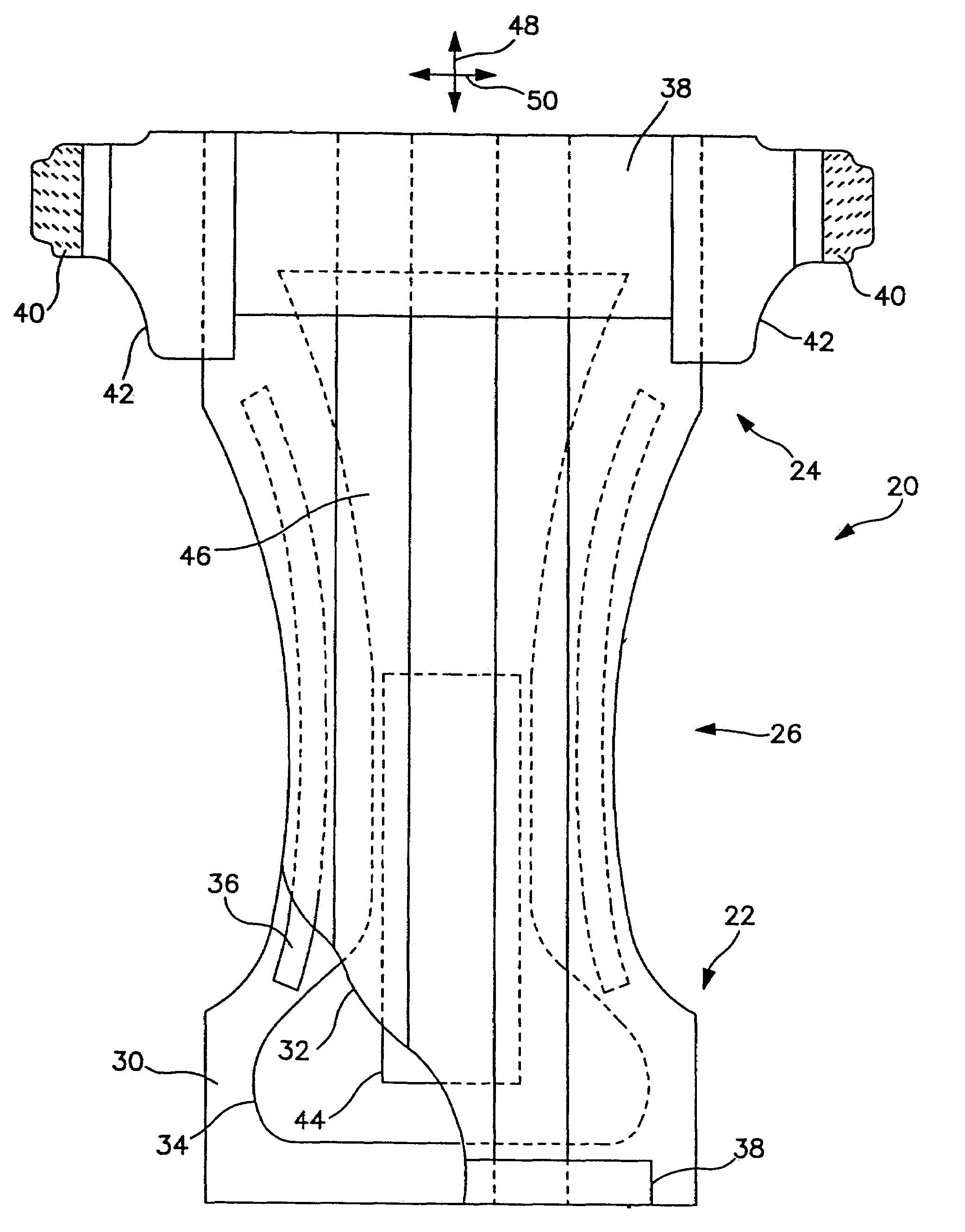
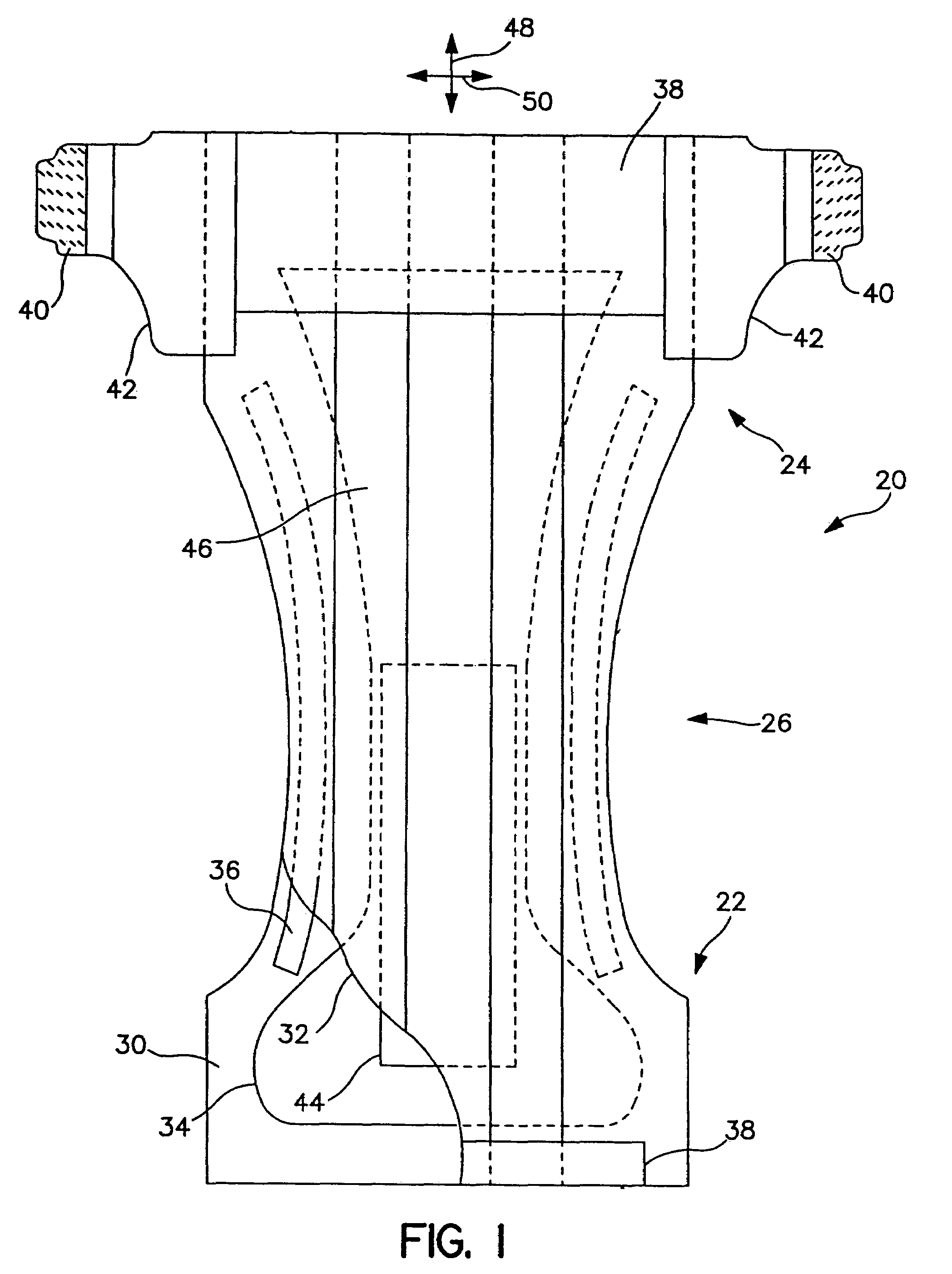
[0067]FIG. 1 is a representative plan view of an absorbent article, such as disposable diaper 20, in its flat-out, or unfolded state. Portions of the structure are partially cut away to more clearly show the interior construction of diaper 20. The surface of the diaper 20 which contacts the wearer is facing the viewer.
[0068]With reference to FIG. 1, the disposable diaper 20 generally defines a front waist section 22, a rear waist section 24, and an intermediate section 26 which interconnects the front and rear waist sections. The front and rear waist sections 22 and 24 include the general portions of the diaper which are constructed to extend substantially over the wearer's front and rear abdominal regions, respectively, during use. The intermediate section 26 of the diaper includes the general portion of the diaper that is constructed to extend through the wearer's crotch region between the legs. Thus, the intermediate section 26 is an area where repeated liquid surges typically occur in the diaper.
[0069]The diaper 20 includes, without limitation, an outer cover, or backsheet 30, a liquid permeable bodyside liner, or topsheet, 32 positioned in facing relation with the backsheet 30, and an absorbent core body, or liquid retention structure, 34, such as an absorbent pad, which is located between the backsheet 30 and the topsheet 32. The backsheet 30 defines a length, or longitudinal direction 48, and a width, or lateral direction 50 which, in the illustrated embodiment, coincide with the length and width of the diaper 20. The liquid retention structure 34 generally has a length and width that are less than the length and width of the backsheet 30, respectively. Thus, marginal portions of the diaper 20, such as marginal sections of the backsheet 30, may extend past the terminal edges of the liquid retention structure 34. In the illustrated embodiments, for example, the backsheet 30 extends outwardly beyond the terminal marginal edges of the liquid retention structure 34 to form side margins and end margins of the diaper 20. The topsheet 32 is generally coextensive with the backsheet 30 but may optionally cover an area which is larger or smaller than the area of the backsheet 30, as desired.

Problems solved by technology

However, in such constructions the fibers of the web still remain in the plane of the web, it is only the plane of the web itself which has been distorted.

Method used


Image

  • Strong high loft low density nonwoven webs and laminates thereof
  • Strong high loft low density nonwoven webs and laminates thereof
  • Strong high loft low density nonwoven webs and laminates thereof

Examples


example 1

[0130]Example 1, was produced according to the present invention to a basis weight of 202 gsm (5.96 osy), with a bulk of 12.6 mm (0.5 inch) and density of 0.016 g / cc. The average denier was measured to be approximately 3.3 dpf (denier per fiber). The fibers were side by side bicomponent, featuring polymer A of Dow 61800.41 polyethylene (PE) and polymer B of Exxon 3155 polypropylene (PP). A TiO2 additive from the Standridge Color Corporation, of Social Circle, Ga., tradenamed SCC-4837, was added to the polymer prior to extrusion at 2% by weight to provide white color and opacity to the web. The fibers were spun through a 96 hole per inch (hpi) spinpack, spinning in an A / B side by side (s / s) configuration, at a melt temperature of 410° F.

[0131]Throughput was balanced in a 50 / 50 throughput ratio between the two polymers, with a total throughput of 0.7 grams per hole per minute (ghm). The quench air temperature was 55° F. The fiber spin length was 48 inches. The fibers were drawn at 4.0...

example 2

[0133]Example 2, was produced according to the present invention to a basis weight of 79 gsm (2.33 osy), with a bulk of 3.8 mm (0.15 inches) and density of 0.021 g / cc. The average denier was measured to be approximately 3.3 dpf. Polymers and additives were the same as stated for Example 1.

[0134]Fiber and web formation conditions were the same as for Example 1 except the forming wire was moving at 220 ft / min, as measured on the forming wire. The HAK was set at 250° F. and 5.0 inches H2O of pressure on bank 1, and 240° F. and 3.5 inches H2O at a height of 5.0 inches above the forming wire. The below wire exhaust under the fiber draw unit was set to vacuum of approximately 1.7 inches H2O in bank 1, and 3.8 inches H2O in bank 2.

example 3

[0135]Example 3, was produced according to the present invention to a basis weight of 77 gsm (2.27 osy), with a bulk of 3.3 mm (0.13 inch) and density of 0.023 g / cc. The average denier was measured to be approximately 3.3 dpf.

[0136]Fiber and web formation conditions were the same as for.Example 1 except the forming wire was moving at 229 ft / min, as measured on the forming wire. The HAK was set at 250° F. and 5.0 inches H2O of pressure on bank 1, and 240° F. and 3.5 inches H2O on bank 2, at a height of 5.0 inches above the forming wire. The below wire exhaust under the fiber draw unit was set to vacuum of approximately 1.6 inches H2O in bank 1, and 3.8 inches H2O in bank 2. The web was bonded at approximately 262-269° F. in a through air bonder.


PUM

PropertyMeasurementUnit
densitiesaaaaaaaaaa
densityaaaaaaaaaa
densityaaaaaaaaaa

Abstract

High loft, low density nonwoven webs suitable for use in a variety of applications requiring strong fabric layers are produced by forming substantially continuous, spunbond, crimped, bicomponent fibers of crimpable, e.g., side by side or eccentric sheath/core (A/B) configuration which are unheated prior to collection. The fibers are then heated and cooled in the absence of impeding forces to achieve maximum crimp in the Z-direction and produce a web of lofted material of greater uniformity than attained with comparable material whose fibers are drawn by a heated process. The resultant nonwoven material can then be pattern bonded or laminated for additional strength without interfering with the desired loft of the low density nonwoven. The additionally strengthened nonwoven may then be further processed such as by lamination or the like to further increase its utility.

Description

[0001]This application claims priority from U.S. provisional application Ser. No. 60 / 479,638 filed 19 Jun. 2003.BACKGROUND OF THE INVENTION[0002]In nonwoven webs, the fibers comprising the web are generally oriented in the X-Y plane of the web and the resulting nonwoven web material is relatively thin, that is lacking in loft or significant thickness. Loft or thickness in a nonwoven web suitable for use in personal care absorbent articles promotes comfort (softness) to the user, surge management and fluid distribution to adjacent layers. In order to impart loft or thickness to a nonwoven web, it is generally desirable that at least a portion of the fibers comprising the web be oriented in the Z-direction. Conventionally, lofty nonwoven webs are produced using staple fibers. See, for example, U.S. Pat. No. 4,837,067 which teaches a nonwoven thermal insulating batt comprising structural staple fibers and bonding staple fibers which are entangled and substantially parallel to the faces...

Claims


Application Information

Patent Timeline
Patent Type & Authority Patents(United States)
IPC IPC(8): D04H3/16B32B5/02B32B27/12D04H1/50
CPCB32B5/02B32B27/12D04H1/50D04H3/163D04H13/002D04H13/007D04H3/16Y10T428/2481D04H3/018D04H3/14B32B2555/02B32B5/26B32B2038/0028B32B5/022B32B2307/51B32B37/0084B32B2307/724B32B2307/7265
Inventor COLLIER, IV, WARREN L.FENWICK, CHRISTOPHER DALEFREESE, CHAD MICHAELBROWN, KURTIS LEESHAWVER, SUSAN ELAINETIMMONS, TERRY KRAMERFITTS, JR., JAMES RUSSELLVARRIALE, MONICA GRACIELANEEB, ALEXANDER J.KEPNER, ERIC SCOTT
Owner KIMBERLY-CLARK WORLDWIDE INC
Why Eureka
Try Eureka