LED light string and arrays with improved harmonics and optimized power utilization

a technology of led light strings and arrays, applied in the direction of lighting and heating apparatus, semiconductor devices for light sources, lighting support devices, etc., can solve the problems of cost effectiveness, long life of leds, and current available sources consuming an order of magnitude less power

Inactive Publication Date: 2004-10-14
FIBER OPTIC DESIGNS
View PDF23 Cites 103 Cited by
  • Summary
  • Abstract
  • Description
  • Claims
  • Application Information

AI Technical Summary

Problems solved by technology

First, as part of an assembly, LEDs have a very long lifespan, compared with common incandescent and fluorescent sources.
Fourth, with newer doping techniques, LEDs are becoming increasingly efficient, and colored LED sources currently available may consume an order of magnitude less power than incandescent bulbs of equivalent light output.
Moreover, with expanding applications and resulting larger volume demand, as well as with new manufacturing techniques, LEDs are increasingly cost effective.
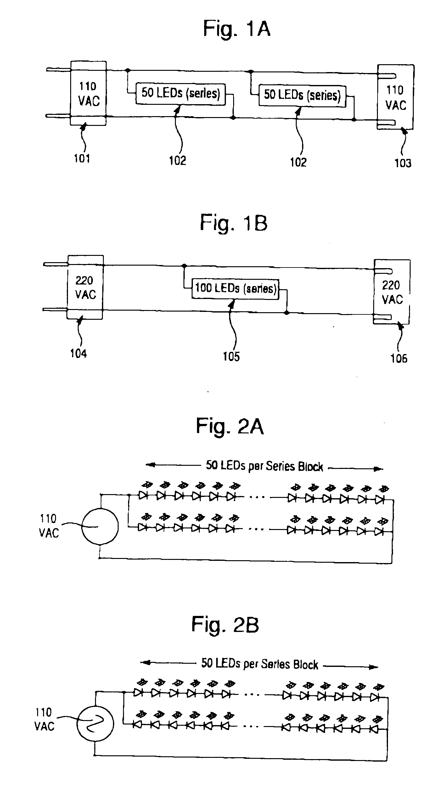
AC driven LED light strings employing a single series block of LEDs, or multiple series blocks of LEDs connected in parallel and oriented in the same polarity exhibit a high percentage of DC and harmonic content as well as poor power utilization.
Harmonic distortion caused by widespread use of AC driven LED light strings presents serious transmission problems to electric utility providers.
However, this is not a truly random event as consumers tend to orient plugs in the same direction.
The "stacking" of plugs, or use of common polarized plugs and end connectors in the construction of LED light strings removes the randomness factor entirely, further exacerbating DC and harmonic feedback problems.
AC driven LED light strings employing multiple series blocks connected in parallel will exhibit the same unbalanced waveform and percent harmonic content as single series block LED light strings when the series blocks are arranged in the same polarity.

Method used


Image

  • LED light string and arrays with improved harmonics and optimized power utilization
  • LED light string and arrays with improved harmonics and optimized power utilization
  • LED light string and arrays with improved harmonics and optimized power utilization

Examples


Embodiment Construction

[0046] Reference will now be made in detail to the presently preferred embodiments and methods of the invention as illustrated in the accompanying drawings, in which like reference characters designate like or corresponding parts throughout the drawings. It should be noted, however, that the invention in its broader aspects is not limited to the specific details, representative assemblies and methods, and illustrative examples shown and described in this section in connection with the preferred embodiments and methods. The invention according to its various aspects is particularly pointed out and distinctly claimed in the attached claims read in view of this specification, and appropriate equivalents.

[0047] It is to be noted that, as used in the specification and the appended claims, the singular forms "a," "an," and "the" include plural referents unless the context clearly dictates.

[0048] The term "alternating current voltage", sometimes abbreviated as "VAC", as used herein occasio...


PUM


Abstract

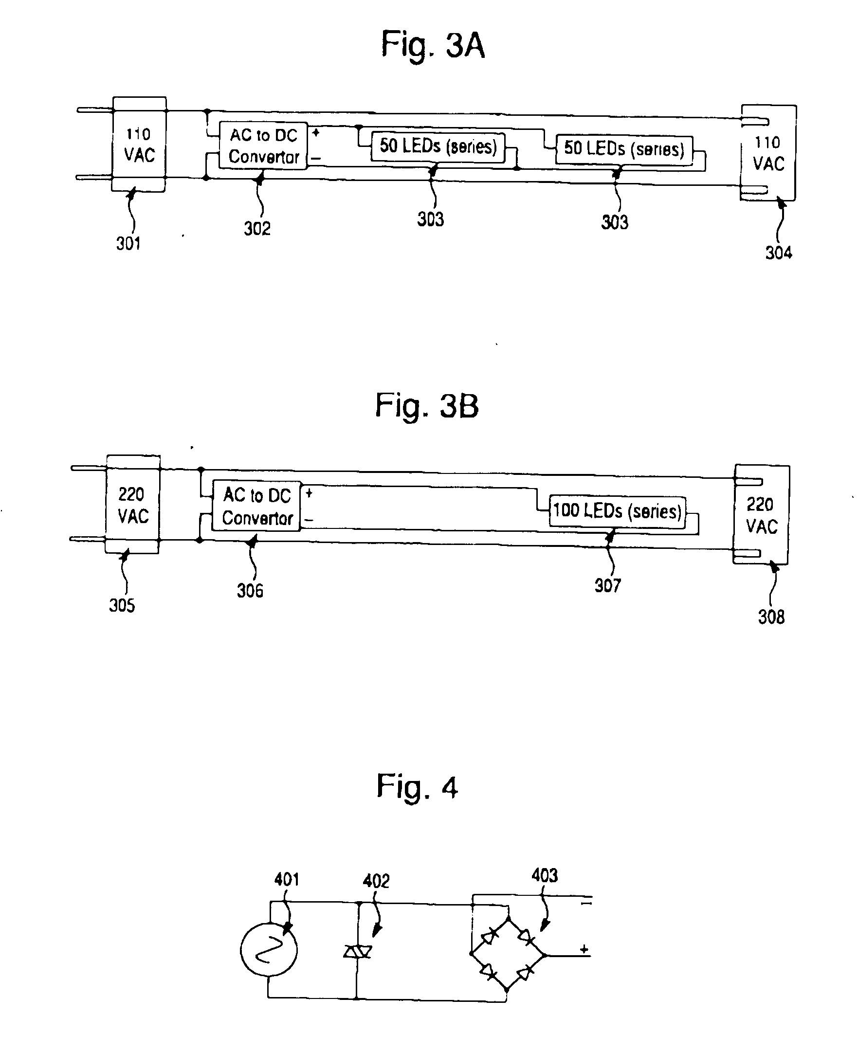
An AC driven LED light string assembly is provided possessing reduced harmonic distortion and improved electrical efficiency when one or more series blocks of LED lamps is employed. In one embodiment, there is provided an LED light string employing a capacitor coupled in parallel across the light string AC input, or end connector terminals. According to another embodiment, LED light strings are to be manufactured with a substantially equal number of light strings produced with all LEDs in forward bias (anode first) and reverse bias (cathode first). This allows true randomness when large numbers of single series block LED light strings are connected in an end-to-end manner. It is possible to apply this concept to single LED lamps having two chips where one chip is powered in reverse bias to the second chip; thereby providing self-canceling harmonics within the single LED lamp.

Description

[0001] This application is a continuation-in-part of application Ser. No. 10 / 243,835 filed Sep. 16, 2002, which is a continuation of copending application Ser. No. 09 / 819,736 filed Mar. 29, 2001, which is a continuation-in-part of copending application Ser. No. 09 / 378,631 filed Aug. 20, 1999, which is a continuation-in-part of copending application Ser. No. 09 / 339,616 filed Jun. 24, 1999. This application claims benefit of U.S. Provisional Application No. 60 / 119,804, filed Feb. 12, 1999. The disclosures of the aforementioned applications are incorporated herein by reference.[0002] 1. Field of Invention[0003] The present invention relates to light emitting diode assemblies, light strings comprising a plurality of light emitting diode assemblies, especially light strings employing light emitting diodes, and related methods.[0004] 2. Description of Related Art[0005] Light emitting diodes (LEDs) are increasingly employed as a basic lighting source in a variety of forms, including decora...

Claims


Application Information

Patent Timeline
Patent Type & Authority Applications(United States)
IPC IPC(8): F21S4/00H05B44/00
CPCF21S4/001F21W2121/00F21Y2101/02H05B33/0803H05B33/0821Y02B20/383F21S4/10F21Y2115/10Y02B20/30H05B45/42H05B45/36
Inventor ALLEN, DAVID
Owner FIBER OPTIC DESIGNS
Why Eureka
Try Eureka