
Apparatus and method for determining reforming catalyst degradation

a technology of apparatus and catalyst, which is applied in the direction of combustion air/fuel air treatment, machines/engines, instruments, etc., can solve the problems of slow rate of temperature rise of reforming catalyst after the change in the air-fuel ratio of the mixture, and the difficulty of accurately calculating the oxygen storage ability of the catalys

Inactive Publication Date: 2004-10-21
TOYOTA JIDOSHA KK
View PDF3 Cites 17 Cited by
  • Summary
  • Abstract
  • Description
  • Claims
  • Application Information

AI Technical Summary

Benefits of technology

[0021] Therefore, as the reforming catalyst degrades, the temperature of the downstream side end portion of the reforming catalyst during a reforming reaction becomes higher than it does when the reforming catalyst is operating normally. Accordingly, it is possible to reliably detect degradation of the reforming catalyst by detecting the temperature of the downstream end portion of the reforming catalyst, and determining the extent of degradation of the reforming catalyst based on the detected temperature of the downstream end portion of the reforming catalyst.
[0023] In the reforming catalyst degradation determining apparatus according to this invention, the determining portion may also determine that the reforming catalyst is degraded if, after observing that the temperature on the downstream side of the reforming catalyst detected by the temperature sensor is higher than a predetermined temperature, the temperature detected by the temperature sensor then falls below the predetermined temperature. If the reforming catalyst is degraded, such that the reforming reaction starts to take place at the downstream end portion of the reforming catalyst, the temperature of that end portion rises. However, because that downstream end portion of the reforming catalyst also degrades over time, the temperature of that end portion also decreases after first rising to a peak value. This structure therefore makes it possible to both easily and accurately determine degradation of the reforming catalyst.
[0025] As described above, when the reforming catalyst is degraded, the reforming reaction starts to take place at the downstream end portion of the reforming catalyst. Therefore, as the reforming catalyst degrades, the temperature difference between the upstream end portion of the reforming catalyst and the downstream end portion of the reforming catalyst becomes less and less, until finally the temperature of the downstream end portion of the reforming catalyst becomes higher than the temperature of the upstream end portion of the reforming catalyst. Accordingly, it is also possible to accurately determine degradation of the reforming catalyst by determining the extent of degradation of the reforming catalyst based on the difference between the temperature of the upstream end portion of the reforming catalyst and the temperature of the downstream end portion of the reforming catalyst. Furthermore in this case, it is also possible to easily execute a routine to determine degradation (hereinafter referred to as "degradation determining routine") because it is not necessary that the operating conditions of the reforming catalyst be the same each time the temperature is detected in order to make a determination as to whether the catalyst is degraded.

Problems solved by technology

In actuality, however, it is not easy to accurately calculate the oxygen storage ability of the catalyst.
Accordingly, with the related art, it is in effect difficult to easily and accurately determine degradation of the catalyst.
When the reforming catalyst is degraded, however, the rate at which the temperature of the reforming catalyst rises after the change in the air-fuel ratio of the mixture is slower than it is when the reforming catalyst is operating normally (i.e., when it is not degraded).
However, because that downstream end portion of the reforming catalyst also degrades over time, the temperature of that end portion also decreases after first rising to a peak value.

Method used


Image

  • Apparatus and method for determining reforming catalyst degradation
  • Apparatus and method for determining reforming catalyst degradation
  • Apparatus and method for determining reforming catalyst degradation

Examples


first exemplary embodiment

[0047] (First Exemplary Embodiment)

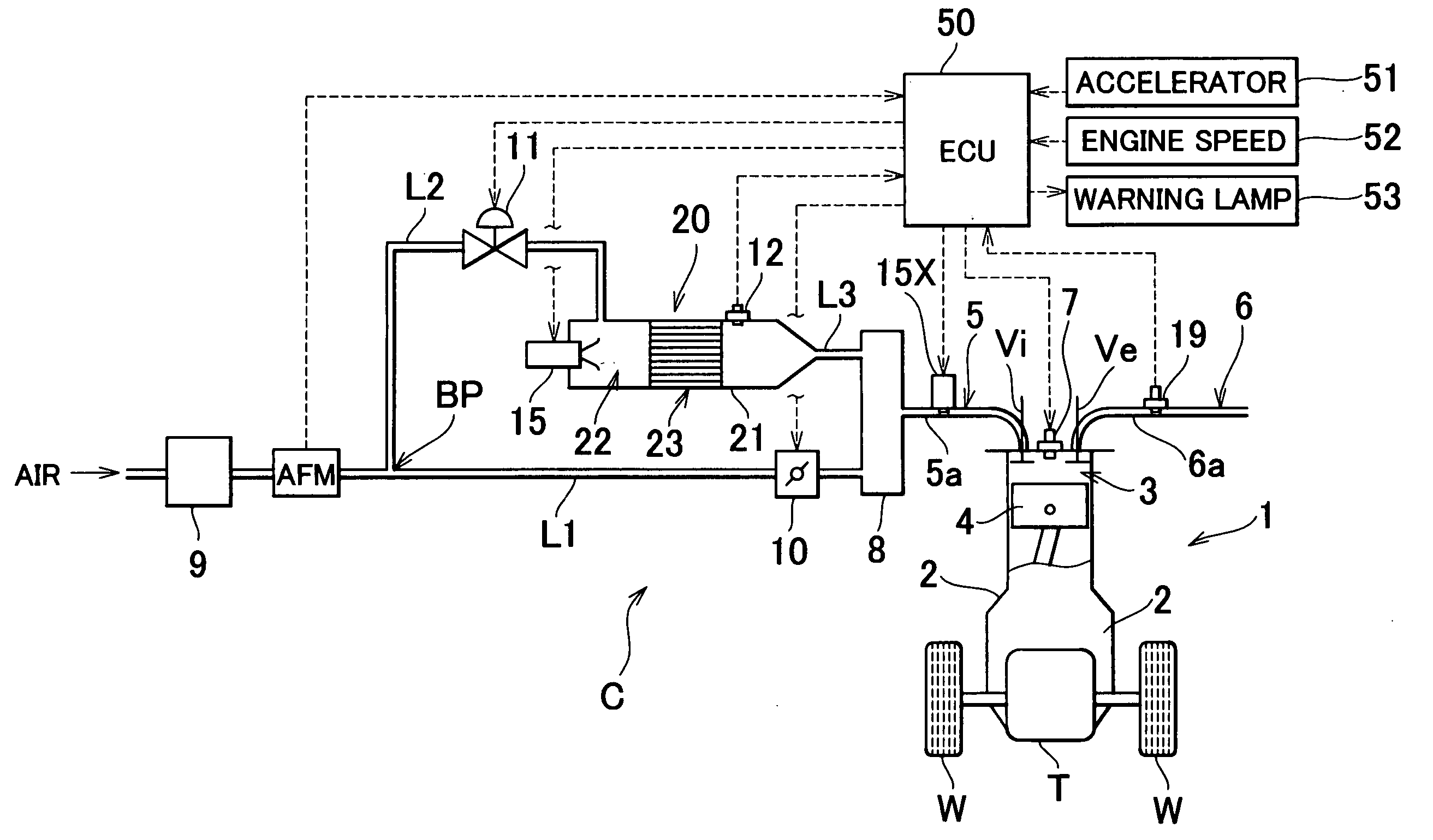
[0048] FIG. 1 is a block diagram schematically showing a vehicle provided with a reformer (i.e., a fuel reforming apparatus) which includes a reforming catalyst degradation determining apparatus according to a first exemplary embodiment of the invention. A vehicle C shown in the drawing has an engine (i.e., internal combustion engine) 1 which serves as a prime mover for running. The engine 1 drives driven wheels W via a transaxle T. The engine 1 generates power by burning a mixture, which includes combustion components, in a combustion chamber 3 of a cylinder formed in an engine block 2 so as to drive a piston 4 back and forth in the cylinder. The engine 1 described in this exemplary embodiment is a multiple cylinder engine (such as a four cylinder engine), but for simplicity, only one of those cylinders is shown in FIG. 1. Subsequently, the following description will refer to the cylinders in the singular.

[0049] The intake port of the cylinder, wh...

second exemplary embodiment

[0077] (Second Exemplary Embodiment)

[0078] A second exemplary embodiment of the invention will now be described with reference to FIGS. 9 to 12. Elements in the second exemplary embodiment which are the same as those in the first exemplary embodiment will be denoted by the same reference numerals, and redundant descriptions thereof will be omitted.

[0079] The partial oxidation reaction in Expression 1 above that progresses in the reforming reaction portion 23 of the reformer 20 according to the invention progresses as an extremely fast rate. Therefore, when the reforming catalyst is not degraded (i.e., when the reforming catalyst is operating normally), a large portion of the fuel and air mixture reacts at the end portion on the upstream side, in the direction of flow of the mixture, (i.e., in the "upstream region") of the reforming catalyst. Therefore, in a reforming catalyst that is not degraded (shown by the solid line in FIG. 9), the temperature at the downstream end portion (i.e...

third exemplary embodiment

[0088] (Third Exemplary Embodiment)

[0089] A third exemplary embodiment of the invention will now be described with reference to FIGS. 13 and 14. Elements in the third exemplary embodiment which are the same as those in the first exemplary embodiment will be denoted by the same reference numerals, and redundant descriptions thereof will be omitted.

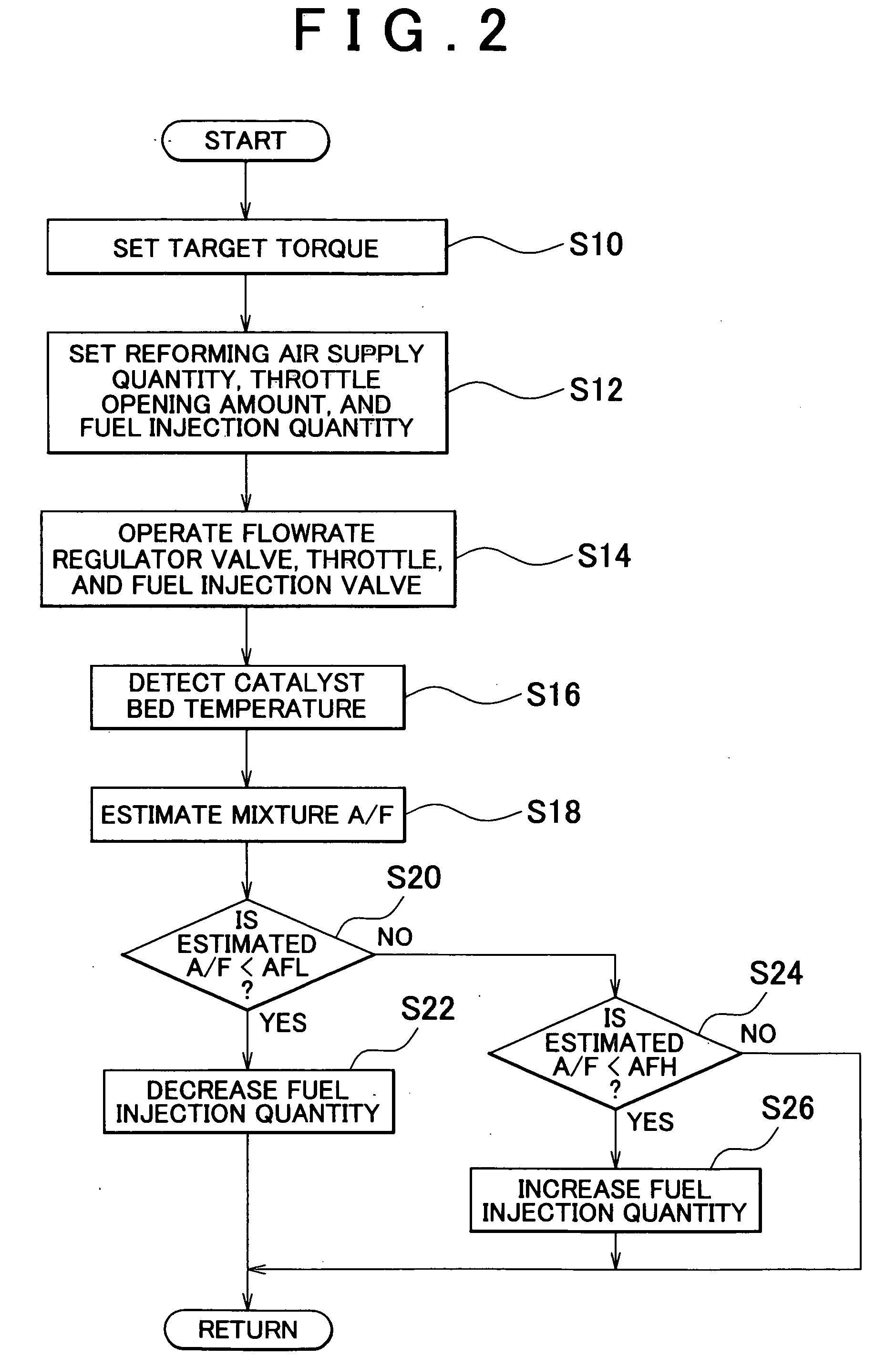
[0090] In the reformer 20 which produces reformate gas that includes CO and H2 through the partial oxidization reaction shown in Expression 1, the catalyst bed temperature (e.g., the average temperature of the reforming reaction portion 23) increases when the mixture to be supplied to the reforming catalyst becomes leaner than a predetermined ratio (i.e., when the value of the air-fuel ratio of the mixture at a given point becomes larger than it has been previously). In this case, if the reforming catalyst is degraded, the rate of increase in the catalyst bed temperature after the air-fuel ratio of the mixture is changed is slower (as shown...


PUM


Abstract

According to an apparatus and method for determining degradation of a reforming catalyst degradation which reforms a mixture of air and fuel, in a reformer that supplies a reformate gas to an engine of a vehicle, a temperature sensor detects a temperature of a reforming reaction portion in which is provided a reforming catalyst. An ECU then determines the extent of degradation of the reforming catalyst based on the temperature detected by the temperature sensor.

Description

INCORPORATION BY REFERENCE[0001] The disclosure of Japanese Patent Application No. 2003-11353 filed on Apr. 18, 2003, including the specification, drawings and abstract is incorporated herein by reference in its entirety.[0002] 1. Field of the Invention[0003] The invention relates to an apparatus and method for determining whether a reforming catalyst, which reforms a mixture of air and fuel, is degraded.[0004] 2. Description of the Related Art[0005] As technology for improving fuel consumption in an engine for a vehicle, an apparatus is known which adds a reformate gas that includes CO and H2 both to fuel to be supplied to the combustion chamber of the engine, as well as to the exhaust gas discharged from the combustion chamber (e.g., JP(A) 2002-54427). This apparatus includes a CO shift catalyst that carries a noble metal on a carrier which has the ability to store oxygen. This CO shift catalyst produces a reformate gas that includes CO and H2 by reforming CO and H2O into H2 and C...

Claims


Application Information

Patent Timeline
IPC IPC(8): C01B3/40F02M27/02
CPCF02M25/12F02M27/02Y02T10/121Y02T10/12
Inventor WAKAO, KAZUHIROSAKURAI, KAZUHIROITOU, TAKAAKIICHINOSE, HIROKI
Owner TOYOTA JIDOSHA KK
Learn More