Method to form reduced dimension pattern with good edge roughness

a technology of edge roughness and dimension pattern, which is applied in the field of lithography, can solve the problems of many cd (critical dimension) reduction methods in the prior art that do not have sufficient cd tolerance, and achieve the effects of improving edge roughness, reducing edge roughness, and strengthening the development process

Inactive Publication Date: 2004-10-28
HEADWAY TECH INC
View PDF8 Cites 10 Cited by
  • Summary
  • Abstract
  • Description
  • Claims
  • Application Information

AI Technical Summary

Benefits of technology

0014] Still another object of at least one embodiment of the present invention has been that said line feature, after processing, have minimum edge roughness.
0015] A further object of at least one embodiment of the present invention has been to provide a process for controlled CD reduction without an accompanying increase in edge roughness.
0016] These objects have been achieved by applying a second Ebeam exposure after the initial one that is used to define the pattern. After this second blanket exposure a longer heat treatment and a stronger development process than before are used. Since the line is already formed at this point, fewer forward scattering electrons are generated at the edge of the resist features, so only edges will be dissolved in a concentrated developer. In addition to reducing edge roughness the disclosed treatment allows the CD to be reduced under tight control since the amount of CD reduction is proportional to the second Ebeam dosage.

Problems solved by technology

Many CD (critical dimension) reduction methods in the prior art do not have sufficient CD tolerance because LER has also increased substantially.

Method used


Image

  • Method to form reduced dimension pattern with good edge roughness
  • Method to form reduced dimension pattern with good edge roughness

Examples


Embodiment Construction

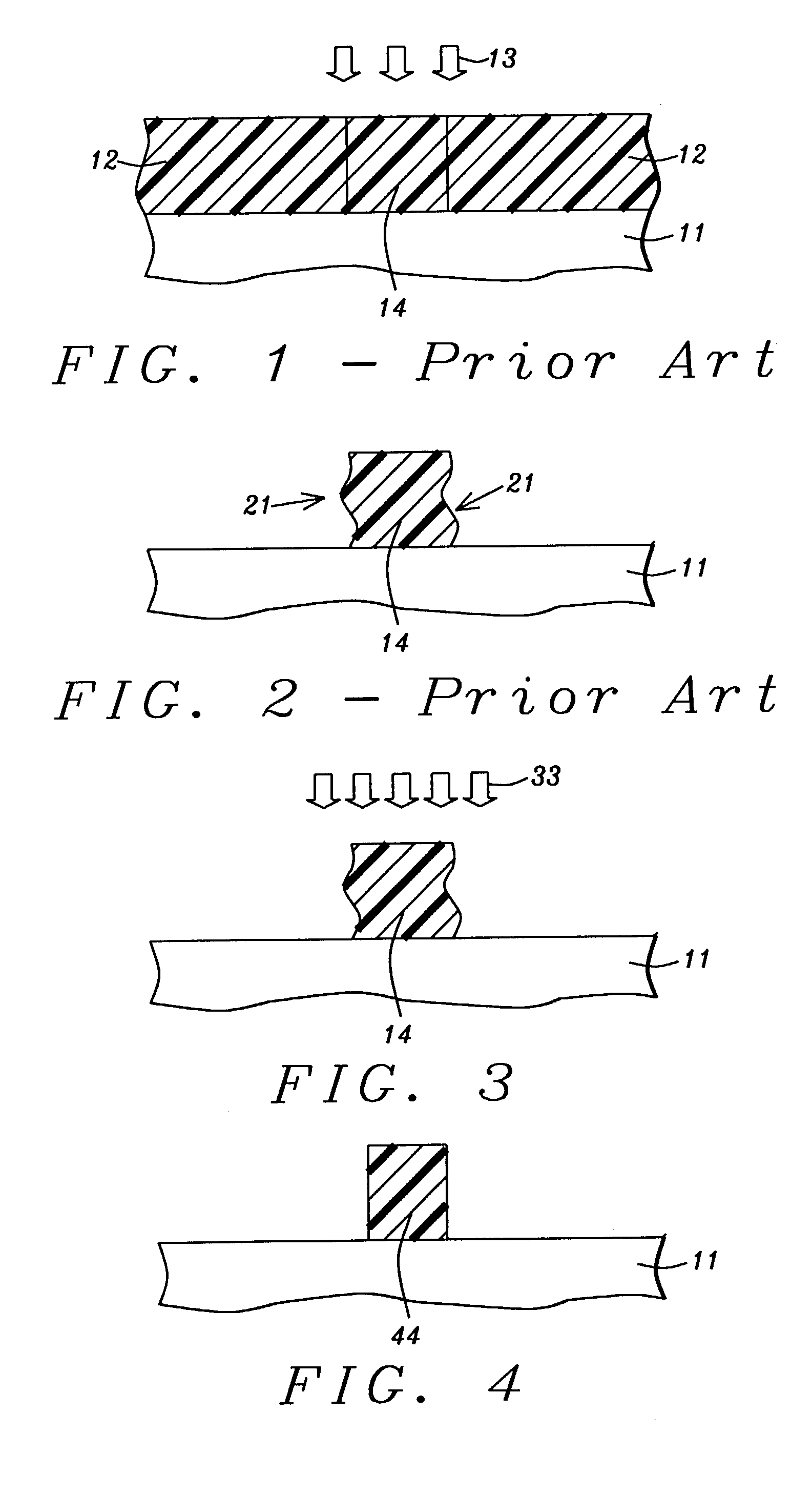
[0023] In the present invention, we apply an extra Ebeam exposure to provide further curing of the developed resist. The disclosed CD-slimming process incorporates additional E-beam exposure, post exposure bake, and resist development steps to the conventional process. Since fewer forward scattering electrons are generated at the edge of resist features, the edge resists will have less degree of cross-linking as compared to the bulk resists. Therefore, only edge resists will be dissolved in the concentrated developer. The disclosed dimension-slimming process allows us to preserve the feature shape without reducing resist thickness or increasing its LER.

[0024] Referring once more to FIG. 1, the process of the present invention begins with providing substrate 11 and then coating with layer of resist 12. Under software control, resist layer 12 is then selectively exposed to electron beam 13 so that region 14 becomes polymerized, as described above, thereby forming a latent image, in th...


PUM

PropertyMeasurementUnit
roughnessaaaaaaaaaa
roughnessaaaaaaaaaa
widthaaaaaaaaaa

Abstract

As feature sizes approach 0.1 .mu.m or smaller, reduction of line edge roughness (LER) becomes increasingly important. Significant reductions in edge roughness have been achieved by applying a second Ebeam exposure after the initial one thatis used to define the pattern. After this second blanket exposure a longer heat treatment and a stronger development process than before are used. In addition to reducing edge roughness the disclosed treatment allows the CD to be reduced under tight control since the amount of CD reduction is proportional to the second Ebeam dosage.

Description

FIELD OF THE INVENTION[0001] The invention relates to the general field of lithography with particular reference to control of line width and edge roughness after electron beam exposure.BACKGROUND OF THE INVENTION[0002] Negative-tone chemically amplified resists (NCAR) have been widely used in electron beam lithography for small dots or fine iso-lines. In general, NCAR, contains base resin, photo acid generator, curing agent, and additives such as a quencher. Referring now to FIG. 1, when NCAR 12 (on substrate 11) is exposed to an electron beam 13, a photo acid generator will release acid in exposed region 14, which will catalyze the cross-linking reaction of the base resin in the subsequent baking process. The degree of cross-linking will influence the dissolution rate of exposed NCAR allowing a resist pattern to be developed through the differential dissolution rates.[0003] As the feature sizes approach 0.1 .mu.m or smaller, reduction of line edge roughness (LER) becomes increasin...

Claims


Application Information

Patent Timeline
Patent Type & Authority Applications(United States)
IPC IPC(8): G03C5/00G03F7/00G03F7/30G03F7/38G03F7/40
CPCG03F7/30G03F7/40G03F7/38
Inventor CHEN, CHAO PENGLUO, CHUNPINGKAO, STUARTCHANG, JEI-WEI
Owner HEADWAY TECH INC
Why Eureka
Try Eureka