
Vibration damping coupling

a vibration damping coupling and expansion-type technology, applied in the direction of pipe joints, flexible pipes, adjustable joints, etc., can solve the problems of insufficient vibration damping ability, low productivity of vibration damping, and complicated pipe structure, and achieve high vibration damping effect and simple structur

Inactive Publication Date: 2004-11-18
SANKAI GIKEN
View PDF16 Cites 34 Cited by
  • Summary
  • Abstract
  • Description
  • Claims
  • Application Information

AI Technical Summary

Benefits of technology

The present invention provides a vibration damping bellows with a simple structure and high vibration damping effects. The bellows has a viscoelastic member between the inner and outer members, which can damp vibrations transmitted through the pipe. The inner and outer members can be made of metal or organic material, and the viscoelastic member can be made of elastomer or silicone rubber. The vibration damping pipe can be used in various applications such as piping for fluid flow. The invention also provides a method for manufacturing the vibration damping coupling with flanges. The technical effects of the invention include effective vibration damping, simple structure, and high manufacturing efficiency.

Problems solved by technology

However, the structure of the pipe is extremely complicated such that productivity thereof is low.
However, since a structure thereof is too complicated and, at the same time, plural layers of the thin plates of the same kind are overlapped therein, vibration damping ability may not be sufficient.
However, since there is no flexibility, it is insufficient as a coupling.
However, in the above conventional vibration damping coupling 500, a vibration damping structure is formed around the movable orifice 502 and thus the structure becomes complicated, so that it is not necessarily desirable.

Method used


Image

  • Vibration damping coupling
  • Vibration damping coupling
  • Vibration damping coupling

Examples


Embodiment Construction

[0040] Hereunder, the present invention is explained in detail in reference to the drawings. The present invention, however, is not limited to the embodiments. Further, constituting elements of the embodiments may include one that can easily be replaced by a person skilled in the art, and substantially the same one.

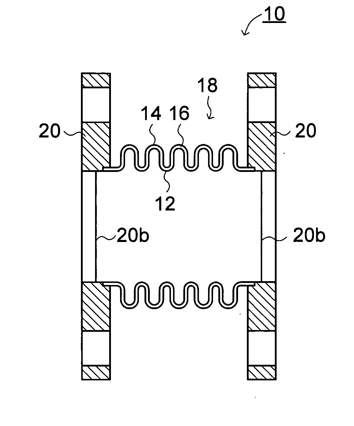
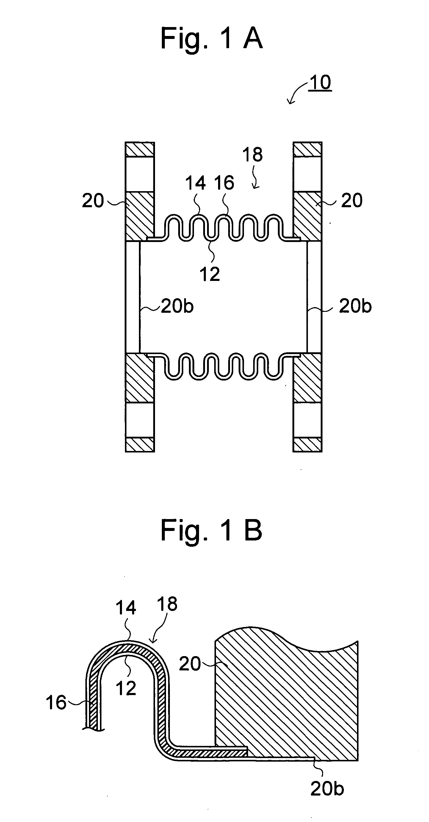
[0041] FIG. 1A is a sectional view showing a vibration damping coupling according to the embodiment of the present invention. As shown in FIG. 1A, this vibration damping coupling 10 has a structure that a vibration absorbing rubber 16 as a vibration absorbing layer is interposed between an inner member 12 and an outer member 14 which are made of stainless steel, thereby forming a vibration damping bellows 18. FIG. 1B shows a partially enlarged view thereof. As material of the stainless steel plate, SUS 304 as a typical austenitic stainless steel and SUS 316 containing a low carbon concentration but a high Ni concentration so as to enhance corrosion resistance. Further, at...


PUM

PropertyMeasurementUnit
outer diameteraaaaaaaaaa
thicknessaaaaaaaaaa

Abstract

A vibration damping bellows with a high vibration absorbing effect and whose a simple structure. In a vibration damping coupling, for example, the vibration damping bellows is formed by interposing viscoelastic material, material with low elasticity, or combination thereof between an inner member and an outer member, which are made of stainless steel. The stainless steel inner member and / or outer member may be omitted when occasion demands. The material of the stainless steel plate, for example, may be SUS 304 that is austenitic stainless steel. Further, flanges to perform connection with pipes may be provided in both ends of the bellows. The viscoelastic material may comprise elastomer such as silicone rubber and vibration damping alloy.

Description

[0001] This application is based upon and claims the benefit of priority from the prior Japanese Patent Application No. 2003-038942 filed on Feb. 17, 2003, the entire contents of which are incorporated herein by reference.[0002] 1. Field of the Present Invention[0003] The present invention relates to an expansible-and-contractible vibration damping pipe, a coupling having the vibration damping pipe, a manufacturing apparatus of the vibration damping pipe, and a forming method of the vibration damping pipe and the like. More specifically, it relates to an expansible-and-contractible vibration damping pipe preventing vibration of a connected piping system and pulsation due to fluid flow in a connected pipe from propagating, a coupling having the vibration damping pipe, a manufacturing apparatus of the vibration damping pipe, and a forming method of the vibration damping pipe and the like.[0004] 2. Related Art[0005] As a flexible expansible pipe with an improved vibration absorbing pro...

Claims


Application Information

Patent Timeline
Patent Type & Authority Applications(United States)
IPC IPC(8): F16L27/10F16F15/08F16J3/04F16L11/11F16L27/11
CPCF16L27/11
Inventor HAYASHI, KANEYOSHI
Owner SANKAI GIKEN
Learn More