Inverter control device for driving a motor and an air conditioner

Inactive Publication Date: 2004-11-18
PANASONIC CORP
View PDF14 Cites 20 Cited by
  • Summary
  • Abstract
  • Description
  • Claims
  • Application Information

AI Technical Summary

Problems solved by technology

Therefore, to conform to the IEC standard at high load, in particular, the inductance value of the power factor correcting-re

Method used


Image

  • Inverter control device for driving a motor and an air conditioner
  • Inverter control device for driving a motor and an air conditioner
  • Inverter control device for driving a motor and an air conditioner

Examples


embodiment 1

[0054] Embodiment 1

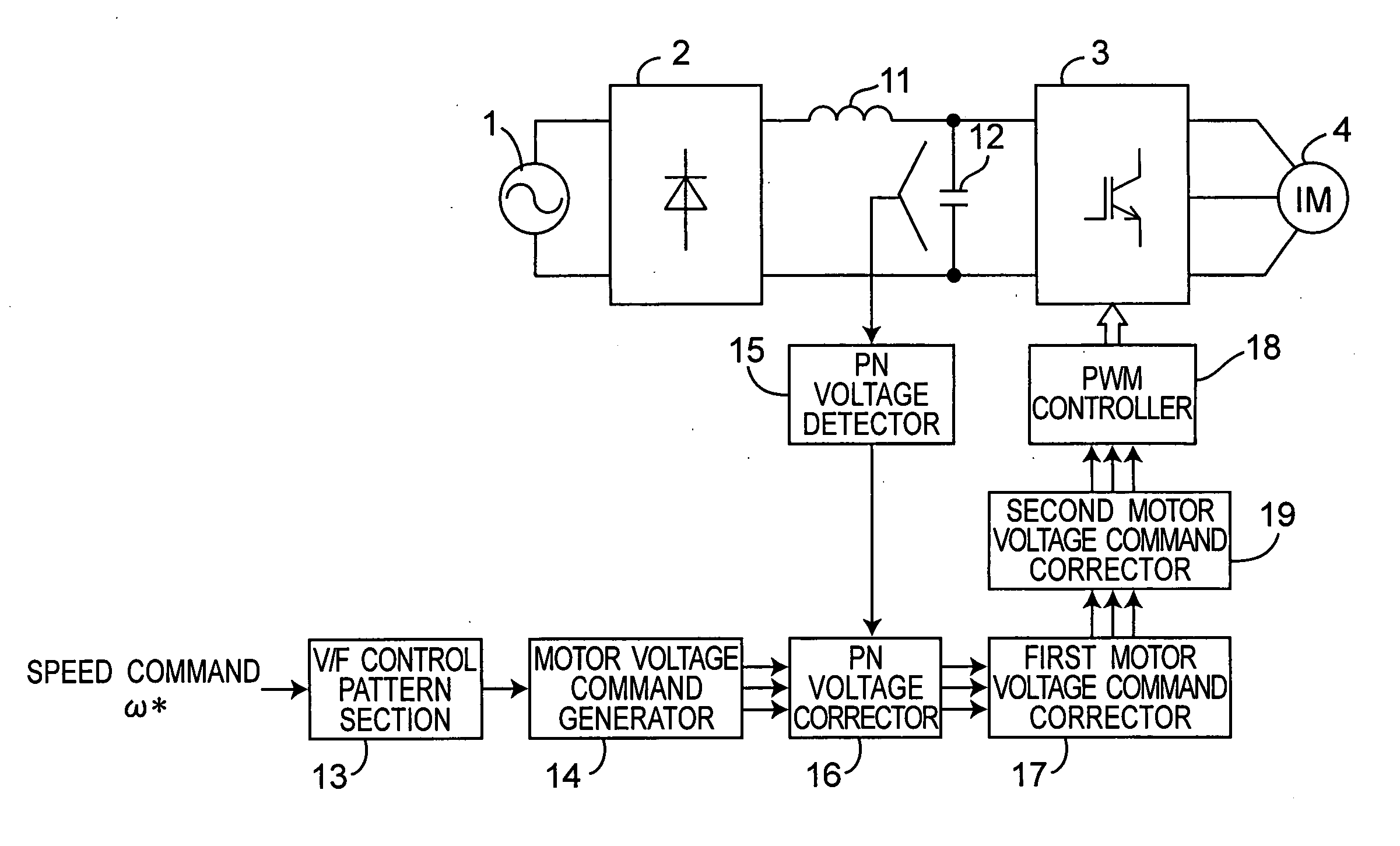
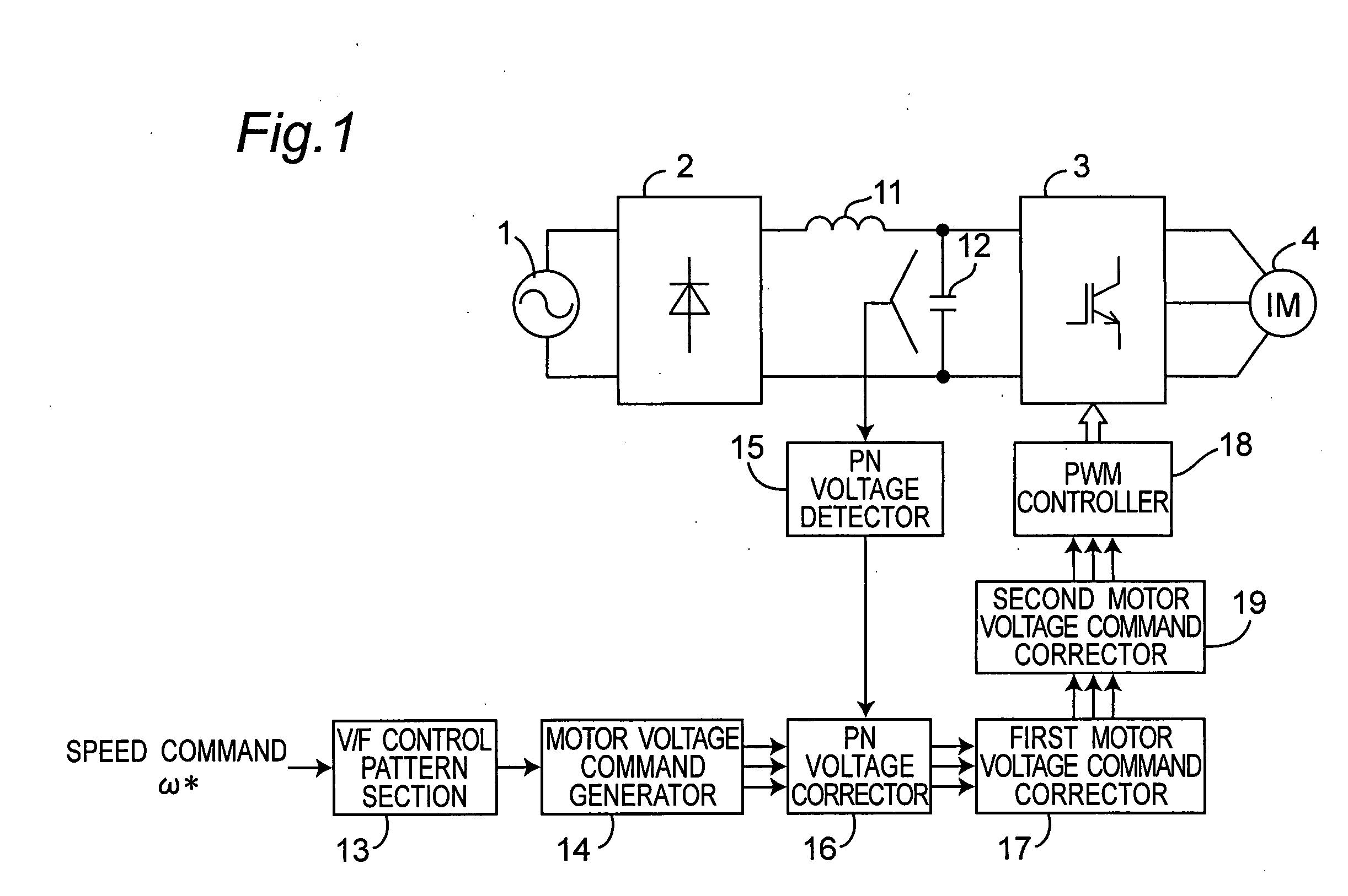
[0055] FIG. 1 is a system block diagram of inverter control device for driving an induction motor in preferred embodiment 1 of the invention. In FIG. 1, a main circuit of the inverter control device includes an AC power source 1, a diode bridge 2 for converting the AC power into a DC power, a reactor 11 of small capacity of 2 mH or less, a capacitor 12 of small capacity of 100 .mu.F or less, an inverter 3 for converting the DC power into an AC power, and an induction motor 4 driven by the AC power converted by the inverter 3.

[0056] On the other hand, a control circuit of the inverter control device includes a V / F control pattern section 13, a motor voltage command generator 14, a PN voltage detector 15, a PN voltage corrector 16, a motor voltage command corrector 17, a PWM controller 18, and the second motor voltage command corrector 19.

[0057] The V / F control pattern section 13 determines the motor voltage value to be applied to the induction motor 4 on the basis ...

embodiment 2

[0075] Embodiment 2

[0076] FIG. 6 is a system block diagram of an inverter driving device for driving an induction motor in the second preferred embodiment of the invention. In FIG. 6, the main circuit is same as in Embodiment 1.

[0077] On the other hand, the control circuit further includes a saturation voltage operator 20 and a motor voltage command maximum value limiting section 21, in addition to the configuration in Embodiment 1.

[0078] The functions of the V / F control pattern section 13, motor voltage command generator 14, PN voltage detector 15, PN voltage corrector 16, and the first motor voltage command corrector 17 are same as in Embodiment 1.

[0079] The saturation voltage operator 20 calculates a reference saturation voltage by multiplying the inverter DC voltage by a value of 1 or more. The second motor voltage command corrector 19 generates the second corrected motor voltage command of the induction motor 4 only when any one of the first corrected motor voltage commands gen...

embodiment 3

[0091] Embodiment 3

[0092] In this preferred embodiment, in calculating the reference saturation voltage V.sub.pn1, the voltage saturation rate is varied depending on the speed command from outside.

[0093] FIG. 8 shows an example of step-wise changes of the voltage saturation rate K in formula (7) depending on the speed command .omega.* of the induction motor 4 given from outside when the reference saturation voltage V.sub.pn1 is calculated by the saturation voltage operator 20 in the inverter control device of Embodiment 2.

[0094] As shown in FIG. 8, By changing step-wise the voltage saturation rate K, the saturation voltage reference value V.sub.pn1 is same value as the DC voltage detection value v.sub.pn, when the speed command .omega.* is less than 100 Hz, and the control is the same as explained in Embodiment 1.

[0095] When the speed command .omega.* is 100 Hz or more, the reference saturation voltage V.sub.pn1 is 1.2 times the detected DC voltage v.sub.pn, and the control is the s...


PUM


Abstract

An inverter control device for driving a motor with small size, light weight and low cost is provided. The inverter control device includes a first motor voltage command corrector that corrects a voltage command of each phase by multiplying the each phase voltage command by a PN voltage correction coefficient, and a second motor voltage command corrector that corrects again the each phase voltage command once corrected by the first motor voltage command corrector, only when any one of the phase voltage commands corrected by the first motor voltage command corrector is larger than the inverter DC voltage, by multiplying the voltage command of each phase corrected by the first motor voltage command corrector by the inverter DC voltage value, and dividing the product of the multiplication by the maximum value of the phase voltage commands corrected by the first motor voltage command corrector.

Description

BACKGROUND OIF THE INVENTION[0001] 1. Technical Field[0002] The present invention relates to an inverter control device for driving a motor and an air conditioner.[0003] 2. Related Art[0004] As an inverter control device for driving a general induction motor used in a general-purpose inverter, for example, an inverter control device for driving an induction motor of V / F controlled system as shown in FIG. 16 is known (see non-patent document 1).[0005] In FIG. 16, the main circuit is composed of a DC (direct-current) power supply apparatus 113, an inverter 3, and an induction motor 4. The DC power supply apparatus 113 includes an AC (alternating-current) power source 1, a rectifying circuit 2, a smoothing capacitor 112 for accumulating electric energy for the DC voltage source of the inverter 3, and a power factor correcting reactor 111 for the AC power source 1.[0006] On the other hand, a control circuit is composed of a V / F control pattern section 13 for determining the motor voltag...

Claims


Application Information

Patent Timeline
IPC IPC(8): F25B1/00H02M5/458H02P23/07H02P23/26H02P27/06H02P27/08
CPCH02M5/458
Inventor MATSUSHIRO, HIDEOKAWAJI, MITSUOSUGIMOTO, TOMOHIRONAKATA, HIDEKIUEDA, MITSUO
Owner PANASONIC CORP
Why Eureka
Try Eureka