Inverter control device for driving a motor and an air conditioner

a technology of inverter control device and motor, which is applied in the direction of motor/generator/converter stopper, dynamo-electric converter control, motor/generator/converter stopper, etc., to achieve the effect of preventing the breakdown of peripheral circuits, small capacity and small capacity

Active Publication Date: 2005-12-06
PANASONIC CORP
View PDF22 Cites 21 Cited by
  • Summary
  • Abstract
  • Description
  • Claims
  • Application Information

AI Technical Summary

Benefits of technology

[0022]In this configuration, using a capacitor with small capacity and a reactor with small capacity, an inverter control device for driving a motor with small size, light weight and low cost can be realized. Further, even though the inverter DC voltage fluctuates largely and motor driving is difficult or even impossible, it is possible to select either an operating region of maintaining stable driving of the motor by operating the inverter so that the voltage applied to the motor may be almost constant, or an operating region of suppressing fluctuations of AC power source current, improving the power factor of AC power source, and suppressing particularly cubic components of harmonic components of AC power source current.
[0024]An inverter operating frequency may be set so as to prevent the inverter operating frequency from stationary fixing in a frequency range having a predetermined margin around the resonant frequency which is a frequency of an even number multiple of AC power source frequency. In this configuration, a resonance phenomenon of inverter frequency and AC power source frequency is avoided, and therefore unstable operation of the motor is prevented and stable driving is realized.
[0026]The capacity of the small capacity capacitor may be determined so that the maximum value of the DC voltage elevating when the inverter is stopped is smaller than withstand voltages of electric devices included in peripheral circuits of the inverter. By determining the capacity of the small capacity capacitor so that the maximum value of the inverter DC voltage may be smaller than the withstand voltage of the driving elements, breakdown of peripheral circuits can be prevented.
[0027]The carrier frequency of the inverter may be determined so that a power factor value of the AC power source is a predetermined value. In this configuration, the predetermined power factor value of the AC power source can be satisfied, and by setting the minimum required carrier frequency, the inverter loss can be suppressed to a lowest limit.
[0028]According to the invention, a voltage command of each phase is corrected appropriately, and thus a capacitor with small capacity and a reactor with small capacity can be used. As a result, an inverter control device for driving a motor with small size, light weight and low cost can be realized. Further, even though the inverter DC voltage fluctuates largely and motor driving is difficult or even impossible, it is possible to select either an operating region of maintaining stable driving of the motor by operating the inverter so that the voltage applied to the motor may be almost constant, or an operating region of suppressing fluctuations of AC power source current, improving the power factor of AC power source, and suppressing particularly cubic components of harmonic components of AC power source current.

Problems solved by technology

Further, even though the inverter DC voltage fluctuates largely and motor driving is difficult or even impossible, it is possible to select either an operating region of maintaining stable driving of the motor by operating the inverter so that the voltage applied to the motor may be almost constant, or an operating region of suppressing fluctuations of AC power source current, improving the power factor of AC power source, and suppressing particularly cubic components of harmonic components of AC power source current.

Method used


Image

  • Inverter control device for driving a motor and an air conditioner
  • Inverter control device for driving a motor and an air conditioner
  • Inverter control device for driving a motor and an air conditioner

Examples


embodiment 1

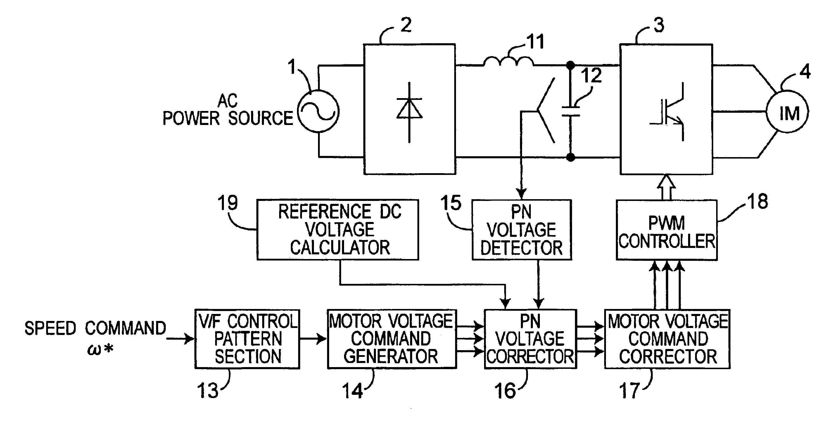
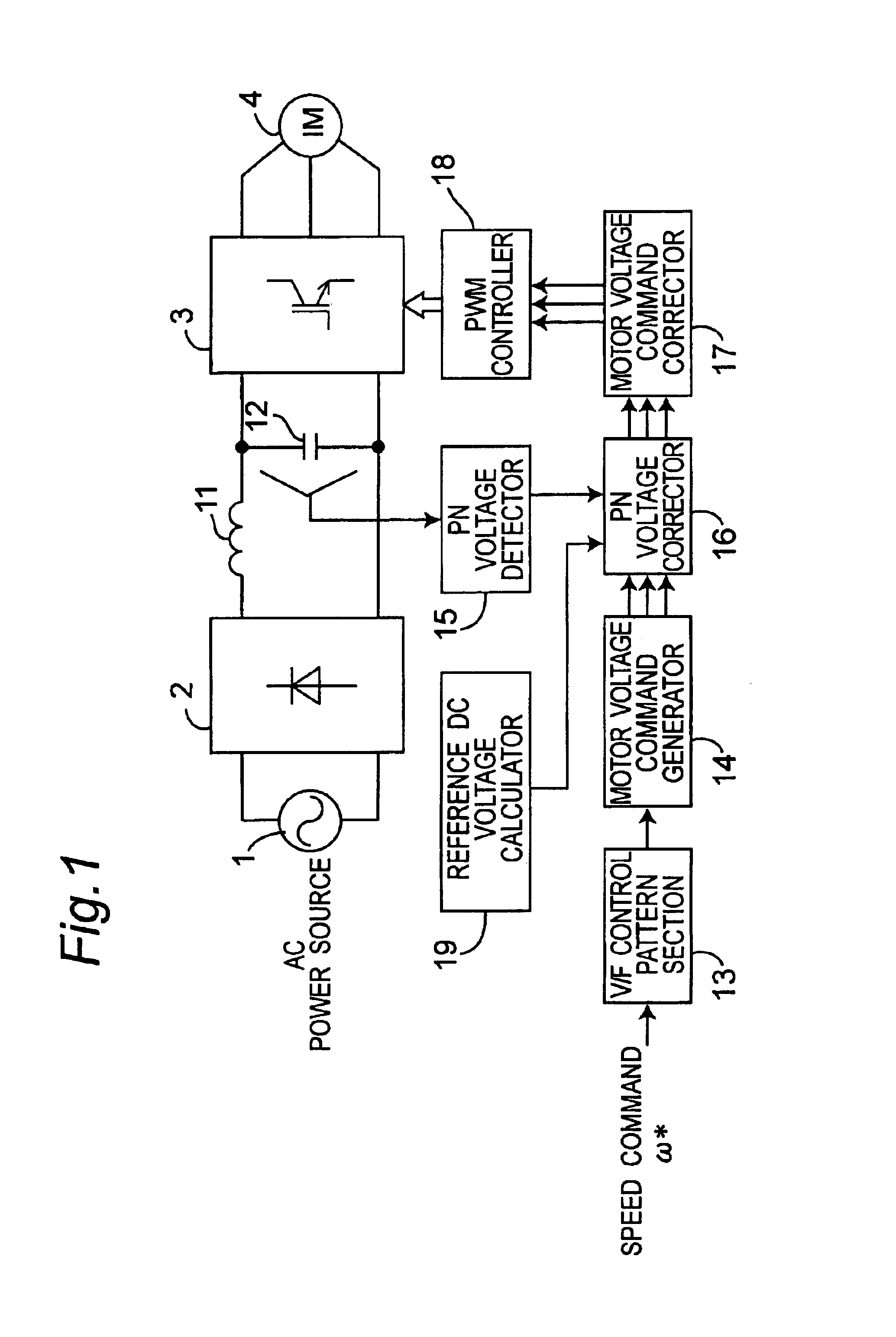
[0051]FIG. 1 is a system block diagram of an inverter control device for driving an induction motor in the preferred embodiment 1 of the invention. In FIG. 1, a main circuit of the inverter control device includes an AC power source 1, a diode bridge 2 for converting the AC power into a DC power, a reactor 11 with small capacity of 2 mH or less, a capacitor 12 with small capacity of 100 μF or less, an inverter 3 for converting the DC power into the AC power, and an induction motor 4 driven by the AC power converted by the inverter 3.

[0052]On the other hand, a control circuit of the inverter control device includes a V / F control pattern section 13, a motor voltage command generator 14, a PN voltage detector 15, a PN voltage corrector 16, a motor voltage command corrector 17, a PWM controller 18, and a reference DC voltage calculator 19.

[0053]The V / F control pattern section 13 determines the motor voltage value to be applied to the induction motor 4 on the basis of the speed command ω...

embodiment 2

[0072]In this preferred embodiment, the reference DC voltage Vpn0 calculated by the reference DC voltage calculator 19 is varied depending on the speed command ω* of the induction motor 4 which is provided from outside.

[0073]FIG. 9 shows an example of change of the reference DC voltage Vpn0 calculated by the reference DC voltage calculator 19 depending on the speed command ω* of the induction motor 4 provided from outside.

[0074]FIGS. 10A and 10B show schematically the operation when the speed command ω* is 80 Hz and 100 Hz with the characteristics of the reference DC voltage calculator 19 shown in FIG. 9.

[0075]In the case of 100 Hz shown in FIG. 10B, as compared with the case of 80 Hz shown in FIG. 10A, the PN voltage correction coefficient kpn is lowered on the whole, and the corrected motor voltage commands vuh*, vvh*, vwh* are suppressed.

[0076]As a result, the induction motor 4 demands more voltage to be applied, and as shown in FIG. 11, the non-flowing period of the AC power sou...

embodiment 3

[0077]A specific setting method of the operating frequency of the inverter according to the present invention is described below.

[0078]Since the inverter control device for driving the induction motor of the invention uses a capacitor with small capacity, the inverter DC voltage pulsates largely at a double frequency of the AC power source frequency fs as shown in FIG. 12.

[0079]Accordingly, at the frequency where the inverter operating frequency f1 is an even number multiple of the AC power source frequency fs, the inverter DC voltage is synchronized with the a pulsating frequency (a double frequency of the AC power source frequency fs), and a resonance phenomenon takes place.

[0080]FIG. 13 shows the operation result when the inverter operating frequency f1 is a double frequency of the AC power source frequency fs. It is known that the inverter DC voltage synchronizes with the pulsating frequency to generate the resonance phenomenon, and a negative DC component is superposed on the m...


PUM


Abstract

An inverter control device for driving a motor with small size, light weight and low cost is provided. The inverter control device generates PN voltage correction coefficient by dividing the reference DC voltage by the detected DC voltage, and corrects the voltage command of each phase by multiplying the voltage command of each phase obtained by the motor voltage command generator with the PN voltage correction coefficient output from the PN voltage corrector, thus resulting in the corrected motor voltage command. The inverter control device has, in generating PN voltage correction coefficient, a first mode in which the PN voltage correction coefficient is set to 1 when the DC voltage value is more than the reference DC voltage, and a second mode in which the value obtained by dividing the reference DC voltage by the detected DC voltage is set to the PN voltage correction coefficient.

Description

BACKGROUND OF THE INVENTION[0001]1. Technical Field[0002]The present invention relates to an inverter control device for driving a motor and an air conditioner.[0003]2. Related Art[0004]As an inverter control device for driving a general induction motor used in a general-purpose inverter, for example, an inverter control device for driving an induction motor of V / F controlled system as shown in FIG. 18 is known (see non-patent document 1, pages 661-711).[0005]In FIG. 18, the main circuit is composed of a DC (direct-current) power supply apparatus 113, an inverter 3, and an induction motor 4. The DC power supply apparatus 113 includes an AC (alternating-current) power source 1, a rectifying circuit 2, a smoothing capacitor 112 for accumulating electric energy for the DC voltage source of the inverter 3, and a power factor correcting reactor 111 for the AC power source 1.[0006]On the other hand, a control circuit is composed of a V / F control pattern section 13 for determining the moto...

Claims


Application Information

Patent Timeline
Patent Type & Authority Patents(United States)
IPC IPC(8): H02P27/06H02P21/05H02P23/04H02P23/07H02P23/26H02P27/08
CPCH02P27/045
Inventor MATSUSHIRO, HIDEOKAWAJI, MITSUOSUGIMOTO, TOMOHIRO
Owner PANASONIC CORP
Why Eureka
Try Eureka