
Method and apparatus for reducing lock time in dual charge-pump phase-locked loops

a phase-locked loop and charge-pump technology, applied in the direction of electrical equipment, angle demodulation by phase difference detection, automatic control, etc., can solve the problem of increased lock time, large error causing large correction, and large voltage ripples

Inactive Publication Date: 2004-12-02
INTEL CORP
View PDF15 Cites 14 Cited by
  • Summary
  • Abstract
  • Description
  • Claims
  • Application Information

AI Technical Summary

Problems solved by technology

As such, a large error causing a large correction is common during the power-up process.
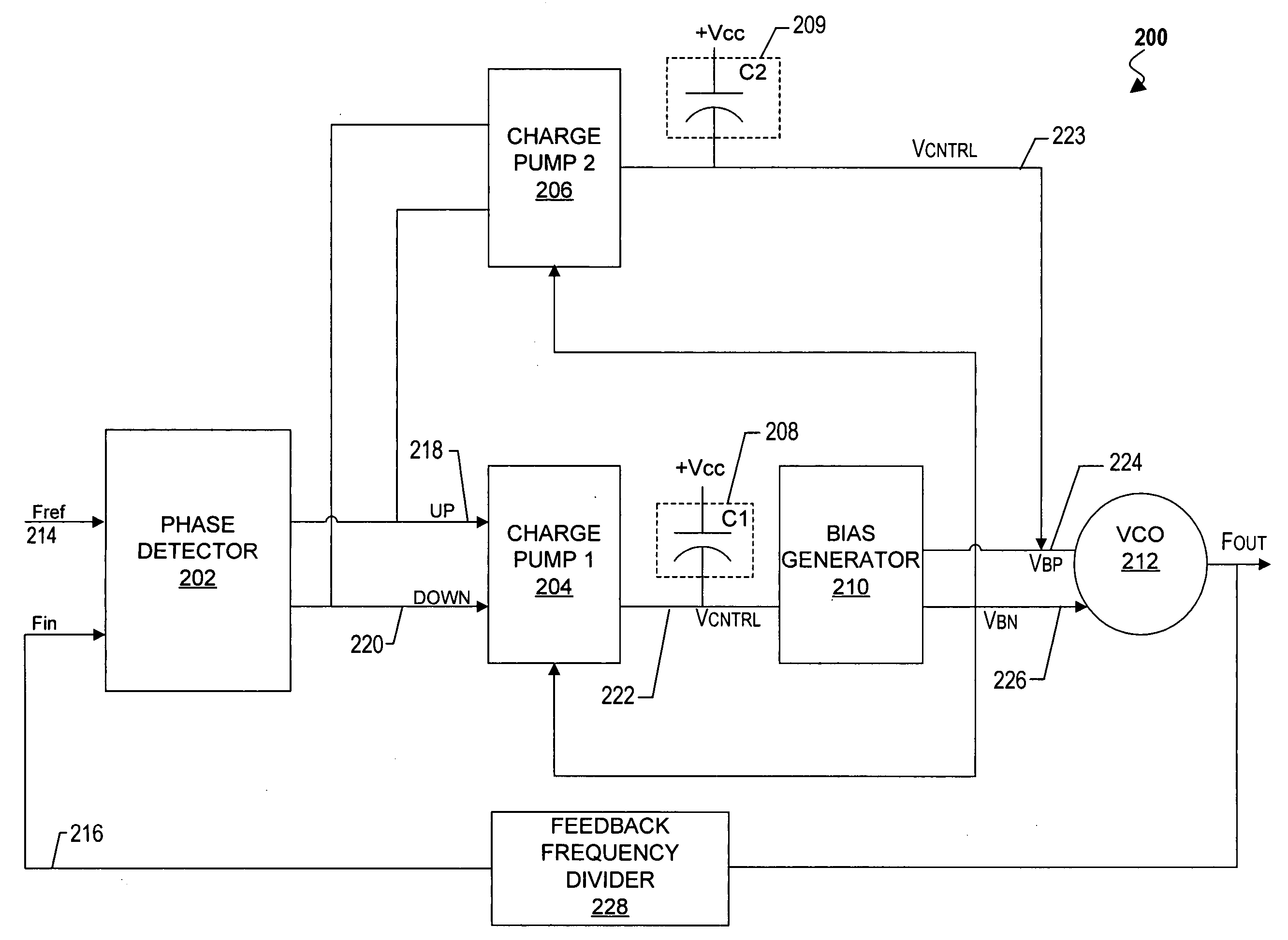
Since the second control voltage is held by only a small storage capacitor, its voltage ripples tend to be large during lock acquisition as a result of large frequency / phase errors.
More specifically, a sufficiently large voltage change can force the VCO out of its linear, functional range resulting in an increased lock time and, in turn, decreased performance.

Method used


Image

  • Method and apparatus for reducing lock time in dual charge-pump phase-locked loops
  • Method and apparatus for reducing lock time in dual charge-pump phase-locked loops
  • Method and apparatus for reducing lock time in dual charge-pump phase-locked loops

Examples


Embodiment Construction

[0017] In the following detailed description, numerous specific details are set forth in order to provide a thorough understanding of the present invention. However, those skilled in the art will understand that the present invention may be practiced without these specific details, that the present invention is not limited to the depicted embodiments, and that the present invention may be practiced in a variety of alternative embodiments. In other instances, well known methods, procedures, components, and circuits have not been described in detail.

[0018] Various operations will be described as multiple discrete steps performed in turn in a manner that is helpful for understanding the present invention. However, the order of description should not be construed as to imply that these operations are necessarily performed in the order they are presented, nor even order dependent. Furthermore, repeated usage of the phrase "in one embodiment" does not necessarily refer to the same embodim...


PUM


Abstract

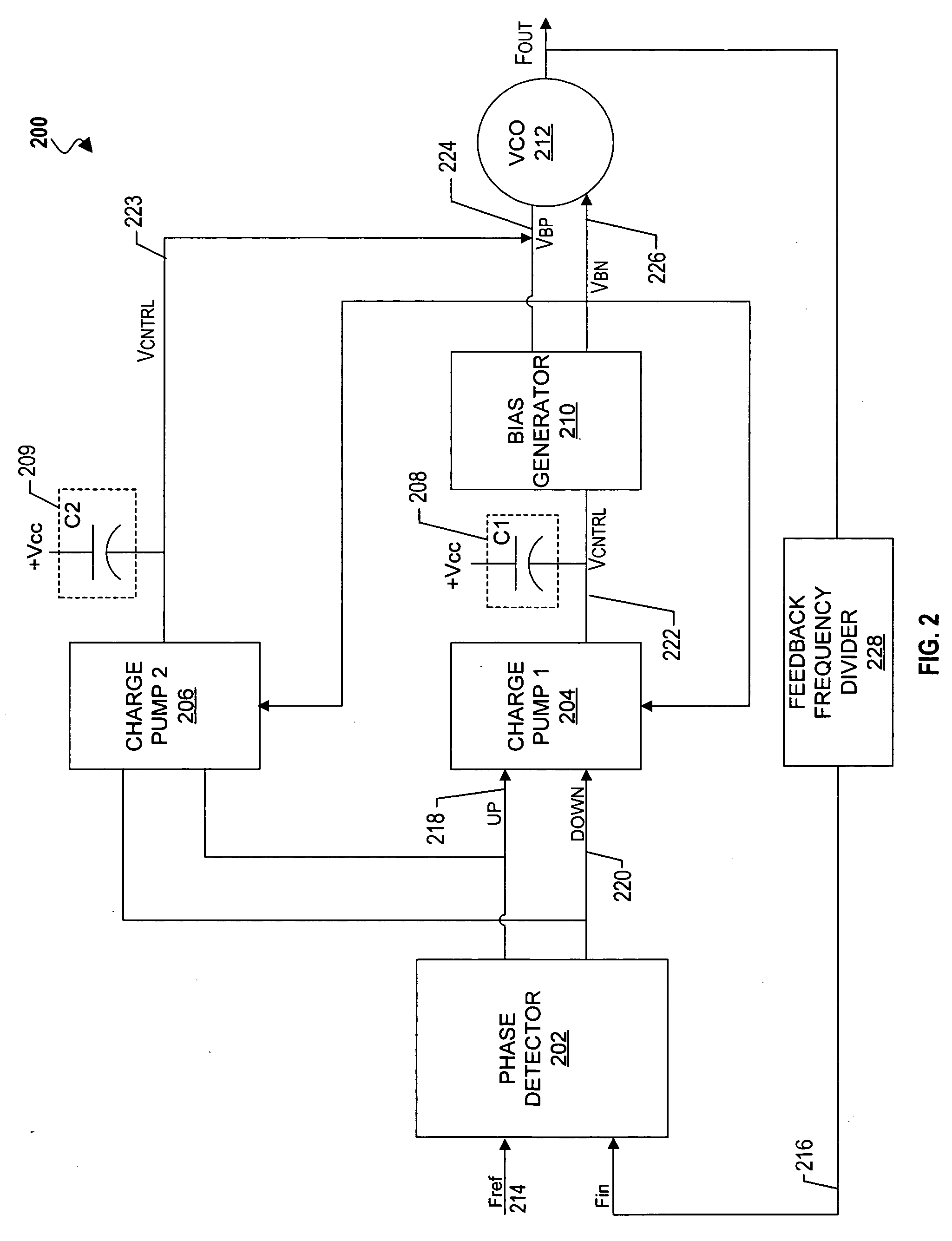
A phase-locked loop includes a phase detector to measure a phase offset between a reference clock signal and a feedback clock signal, and to generate first and second output control signals having a pulse width corresponding to the phase offset. The phase locked loop further includes a first pulse width control circuit coupled to the phase detector to reduce the pulse width of the first output control signal producing a first modified output control signal, a second pulse width control circuit coupled to the phase detector to reduce the pulse width of the second output control signal producing a second modified output control signal, a first charge pump coupled to the phase detector to provide a first charge signal responsive to the first and second output control signals, and a second charge pump coupled to the first and second pulse width control circuits to provide a second charge signal responsive to the first and second modified output control signals.

Description

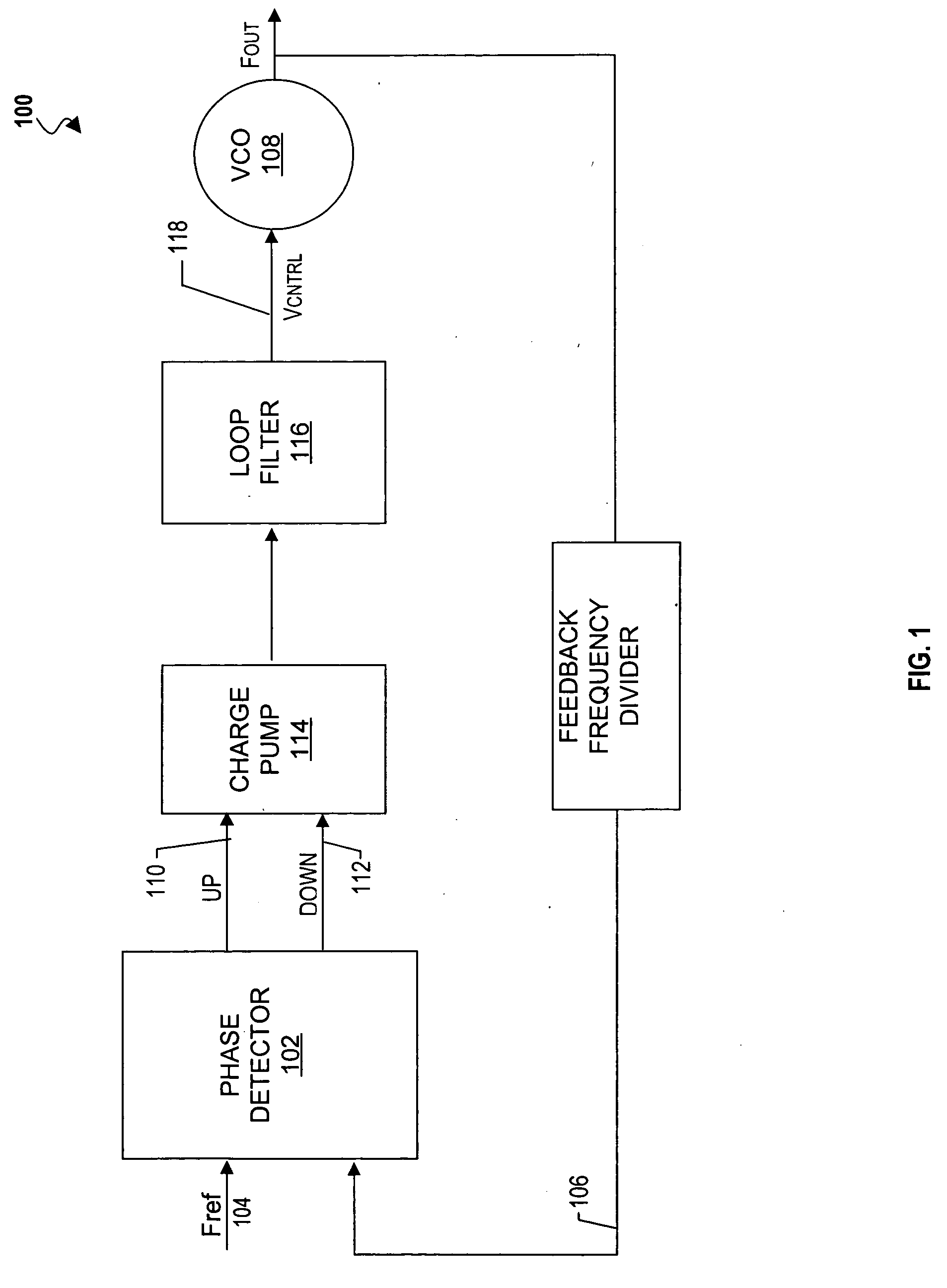
[0001] 1. Field of the Invention[0002] The present invention relates generally to phase-locked loop circuits, and more specifically, to a design to reduce lock-time in a dual charge-pump phase-locked loop.[0003] 2. Background Information[0004] Due to continual advancements in microprocessor design and fabrication techniques, the physical size of microprocessors has been decreased over time, while the clock frequencies of these microprocessors have continually been increased. In order to attain even higher clock frequencies in the future, much attention is currently being focused on increasing clock accuracy by reducing such things as clock skew and jitter, which can adversely affect the timing of a circuit or system.[0005] Phase-locked loops or "PLLs" have been widely used in data communications, local area networks, microprocessors, and data storage applications to generate secondary clock signals based upon a given reference signal. FIG. 1 illustrates a phase-locked loop in accord...

Claims


Application Information

Patent Timeline
Patent Type & Authority Applications(United States)
IPC IPC(8): H03L7/089H03L7/093H03L7/107
CPCH03L7/0893H03L7/093H03L7/107H03L7/1072H03L2207/06
Inventor LIM, CHEE HOWWONG, KENG L.PARKER, RACHAEL
Owner INTEL CORP
Learn More