Cylinder with interchangeable sleeve method of manufacturing the same and associated unit

a technology of cylinder and sleeve, which is applied in the direction of portable power-driven tools, applications, and ways, etc., can solve the problems of reducing the production efficiency of cylinders

a technology of cylinder and sleeve, which is applied in the direction of portable power-driven tools, applications, and ways, etc., can solve the problems of reducing the production efficiency of cylinders

US20040242392A1Inactive Publication Date: 2004-12-02FABIO PERINI SPA

Image

  • Cylinder with interchangeable sleeve method of manufacturing the same and associated unit
  • Cylinder with interchangeable sleeve method of manufacturing the same and associated unit
  • Cylinder with interchangeable sleeve method of manufacturing the same and associated unit

Examples


Embodiment Construction

[0054] A first embodiment of the invention will now be described with reference to FIGS. 1 to 4.

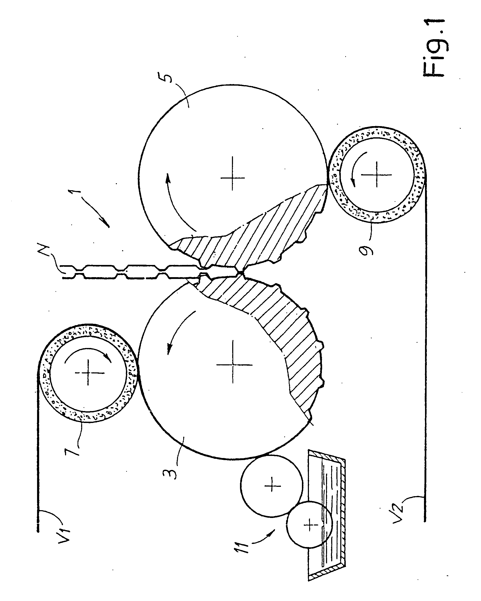
[0055] FIG. 1 shows in very schematic form an embossing unit, generally indicated by 1, in which the present invention may be used. It must however be understood that the principles underlying the invention may also be applied in the manufacture of embossing cylinders intended for embossing units of another type, for example "nested" units or also individual embossers. Moreover, the invention may also be used for the manufacture of cylinders for processing web-like materials, able to perform operations other than embossing, for example printing or other processing operations which require rapid replacement of an interchangeable sleeve fitted onto the cylinder, whenever problems of angular slipping between interchangeable cylinder and central core of the cylinder occur.

[0056] The embossing unit 1 is of the so-called tip-to-tip type and has a first embossing cylinder 3 and a second embossin...


PUM

PropertyMeasurementUnit
Forceaaaaaaaaaa
Pressureaaaaaaaaaa
Diameteraaaaaaaaaa

Abstract

The rotating cylinder comprises: an elongated inner core (12) which is substantially rigid and an interchangeable sleeve (45) which is fitted onto the core; the sleeve is axially and angularly constrained to said core and is provided on its external surface with a raised pattern. The internal surface of the interchangeable sleeve and the external surface of the inner core are conical surfaces which are mutually complementary; axial and angular locking of the interchangeable sleeve and the inner core is achieved by the friction between the conical surfaces which are forced axially one onto the other.

Description

[0001] The present invention relates to a rotating cylinder for processing a web-like material, and in particular but not exclusively to an embossing cylinder for embossing materials in sheet form, such as tissue paper or the like. More particularly, the invention relates to a rotating cylinder of the type comprising a substantially rigid, central, inner core on which an interchangeable sleeve is fitted.[0002] The invention also relates to a device comprising at least one rotating cylinder of the abovementioned type, for example an embossing unit or a printing unit.[0003] The invention also relates to an interchangeable sleeve for a rotating cylinder, in particular an embossing cylinder or a printing cylinder of the type mentioned above.[0004] According to a further aspect, the invention relates to a method for manufacturing embossing cylinders or similar cylinders, such as printing cylinders, for the processing of strip-like materials, such as paper, tissue-paper or the like.STATE ...

Claims


Application Information

Patent Timeline
02 Dec 2004
Publication
US20040242392A1
IPC
B31F1/07
CPC
B31F1/07; B31F2201/072; B31F2201/0723; B31F2201/0728; B31F2201/073; B31F2201/0753; B31F2201/0766; B31F2201/0776
Inventors
BETTI, GIULIO; LORENZI, FABRIZIO