Data conversion apparatus, data conversion system, and data conversion program

Inactive Publication Date: 2004-12-09
KK TOSHIBA
View PDF6 Cites 17 Cited by
  • Summary
  • Abstract
  • Description
  • Claims
  • Application Information

AI Technical Summary

Problems solved by technology

However, it is also difficult under present circumstances to "convert a JPEG file into a bitmap file", for example, in the drag-and-dr

Method used


Image

  • Data conversion apparatus, data conversion system, and data conversion program
  • Data conversion apparatus, data conversion system, and data conversion program
  • Data conversion apparatus, data conversion system, and data conversion program

Examples


Example

First Embodiment

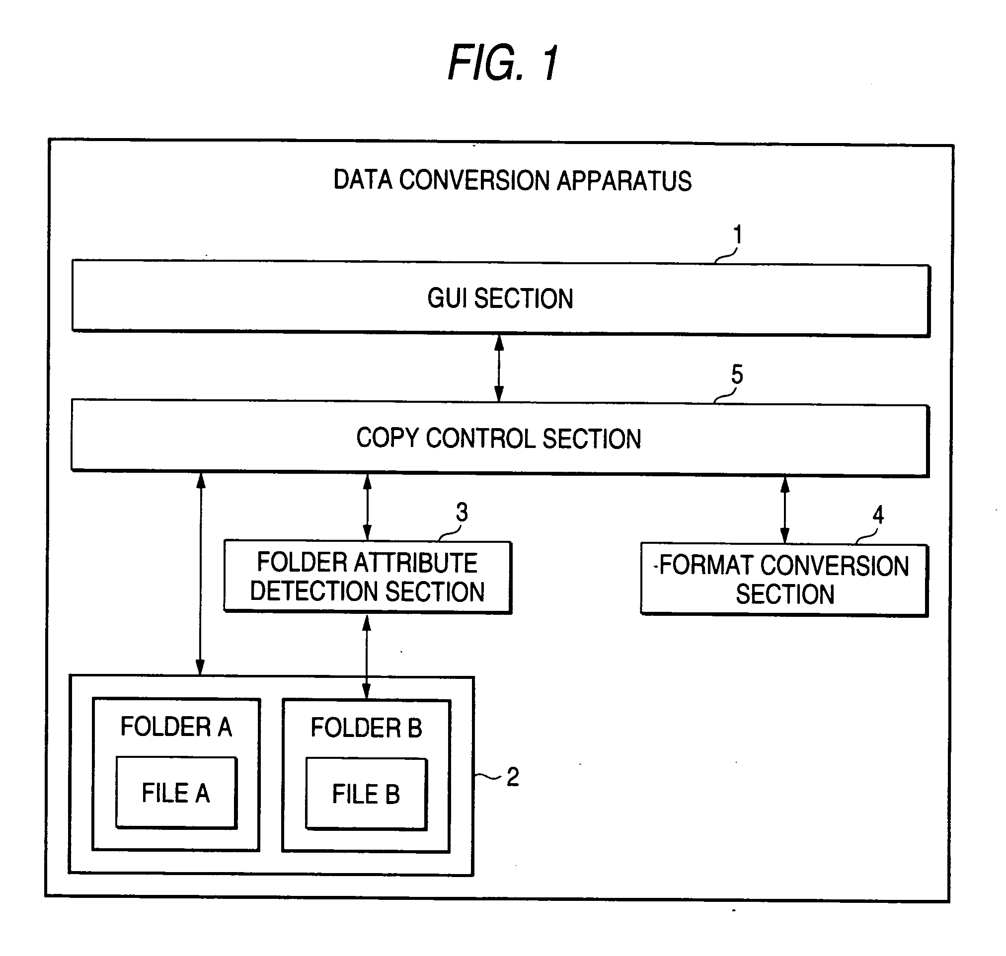
[0036] FIG. 1 is a block diagram to show a schematic configuration of a data conversion apparatus according to a first embodiment of the invention. The data conversion apparatus in FIG. 1 is incorporated in an electronic information machine such as-a personal computer (PC). The data conversion apparatus in FIG. 1 may be implemented as a hardware or software, or a part of the data conversion apparatus may be implemented as a hardware and the remaining parts may be implemented as a software.

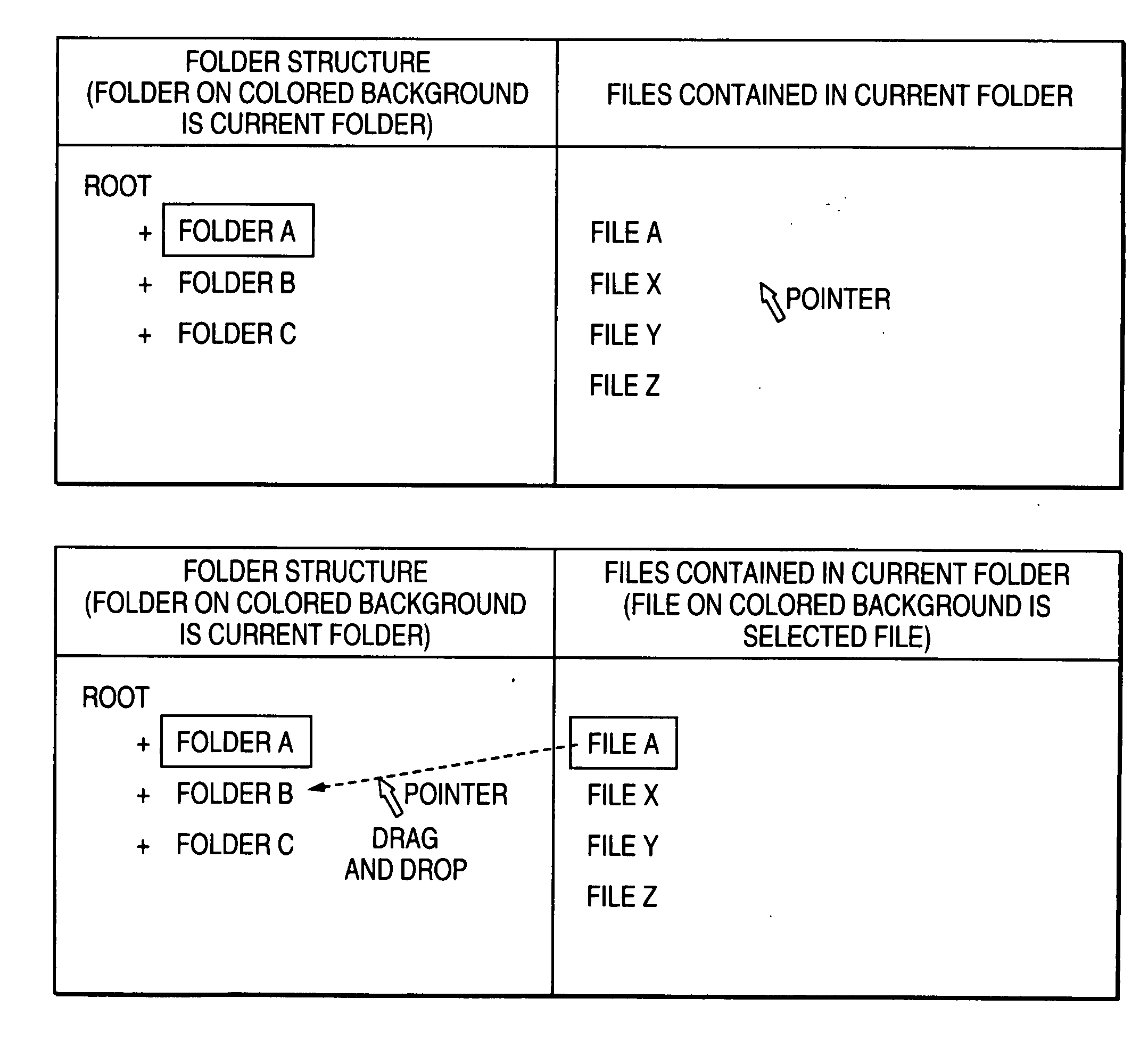
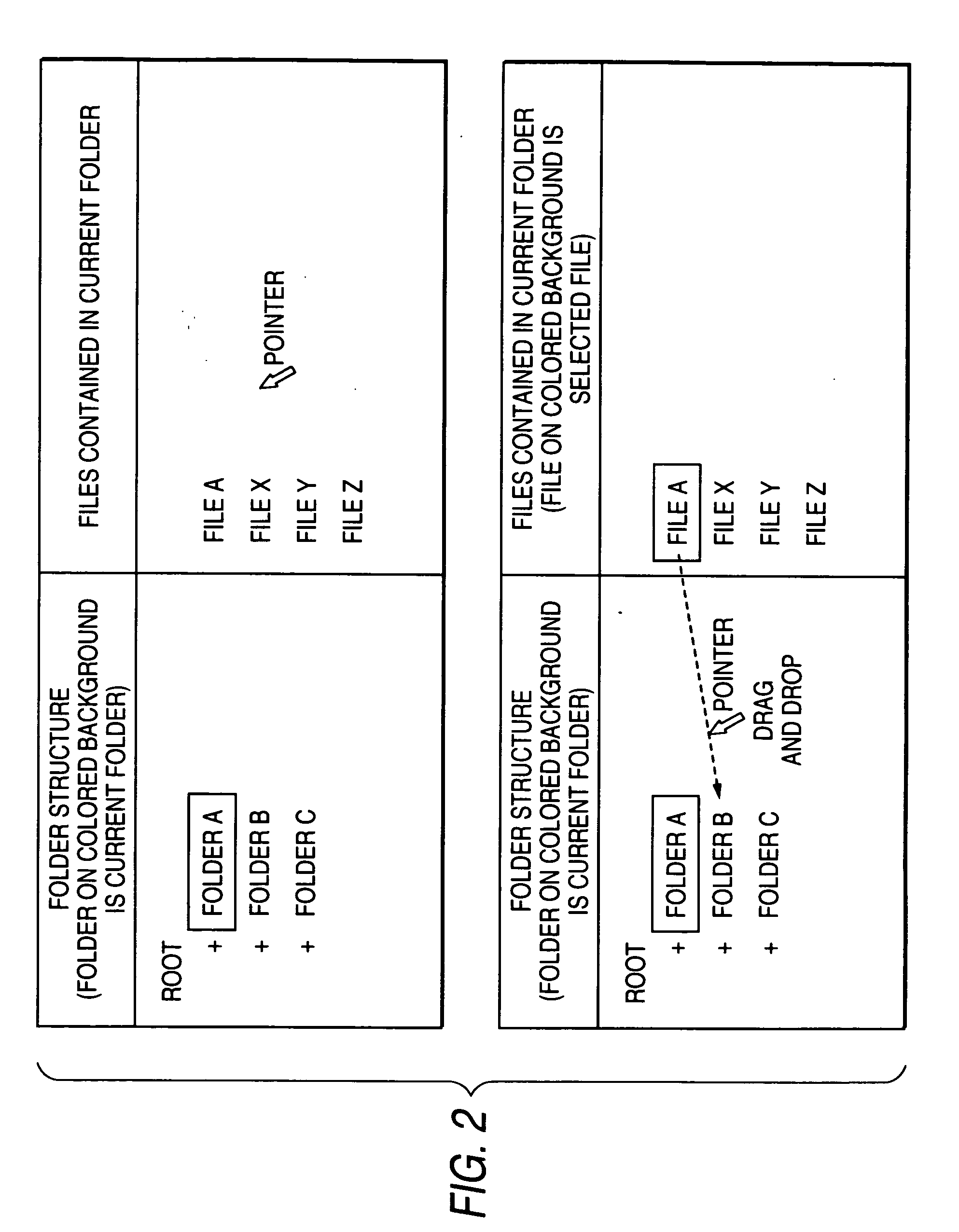
[0037] The data conversion apparatus in FIG. 1 includes a graphical user interface section (GUI section) 1 for copying a file, storage unit 2 for storing electronic data for each folder, a folder attribute detection section 3 for detecting an attribute of each folder in the storage unit 2, a format conversion section 4 for executing a format conversion of electronic data, and a copy control section 5 for controlling the folder attribute detection section 3 and the format conversion ...

Example

Second Embodiment

[0060] A second embodiment of the invention is intended for lightening the process load as compared with the first embodiment.

[0061] FIG. 4 is a block diagram to show a schematic configuration of a data conversion apparatus according to the second embodiment of the invention. A component identical with or similar to that in FIG. 1 is denoted by the same reference numeral in FIG. 4, and the description to follow centers around a difference between the first and second embodiments.

[0062] The data conversion apparatus in FIG. 4 has an image conversion information storage section 6 for storing attribute information of an encoding, a pixel size, etc., that can be converted by a format conversion section 4 in a copy control section 5.

[0063] FIG. 5 is a flowchart to show a procedure example of the data conversion apparatus in FIG. 4. The flowchart of FIG. 5 is provided by adding steps S25, S26, and S29 to the flowchart of FIG. 3. The description to follow centers around di...

Example

Third Embodiment

[0071] In a third embodiment of the invention, image data converted by a format conversion section 4 is stored in a copy control section 5 so that the format conversion section 4 does not repeat image conversion of the same image data.

[0072] FIG. 6 is a block diagram to show a schematic configuration of a data conversion apparatus according to the third embodiment of the invention. A component identical with or similar to that in FIG. 1 is denoted by the same reference numeral in FIG. 6, and the description to follow centers around a difference between the first and third embodiments.

[0073] The data conversion apparatus in FIG. 6 has a history information storage section 7 provided in a storage unit 2 for storing image conversion history information and the converted image data, and a history information storage control section 8 provided in the copy control section 5 for performing storage control of the history information storage section 7.

[0074] FIG. 7 is a flowc...


PUM


Abstract

A data conversion apparatus including a plurality of electronic data storage units storing electronic data with a proper attribute, a storage command unit configured to instruct to store electronic data to be stored in one of the plurality of electronic data storage units, an attribute detection unit configured to detect an attribute of the electronic data to be stored in the electronic data storage unit preassigned the attribute instructed by the storage command unit, a format conversion unit configured to convert a format of the electronic data to be stored so as to fit a format for the attribute detected by the attribute detection unit if the attribute of the electronic data to be stored differs from the attribute detected by the attribute detection unit, and a storage control unit configured to store the electronic data converted by the format conversion unit in the electronic data storage unit as a storage destination.

Description

[0001] 1. Field of the Invention[0002] This invention relates to a data conversion apparatus, a data conversion system, and a data conversion program for storing electronic data in any of a plurality of electronic data storage units.[0003] 2. Background Art[0004] An electronic information machine including an operation system typified by Windows.RTM., Linux.RTM., etc., generally includes a user interface for copying electronic data retained in the electronic information machine to another data, and for providing the copy function for a user using the electronic information machine.[0005] The copy function can be abstracted as description of copy (A, B) as a function. A denotes original data and B denotes copied data. As copy (A, B) is executed, B is created from A.[0006] As the user interface for providing the copy function, for example, the operating system Windows of Microsoft.RTM. provides an application including a command line user interface called a command prompt and an appli...

Claims


Application Information

Patent Timeline
IPC IPC(8): G06F12/00G06F17/00G06F17/30G11B5/86G11B20/10
CPCG06F17/30569G06F16/258
Inventor KAWAMURA, TAKUYA
Owner KK TOSHIBA
Why Eureka
Try Eureka