Rapid catalyst warm-up control device for internal combustion engine

a technology of a control device and a catalyst, which is applied in the direction of electrical control, machines/engines, mechanical apparatus, etc., can solve the problems of delayed injection dither control, insufficient oxidation reaction of rich components in the catalyst, and insufficient delay in catalyst warm-up

Inactive Publication Date: 2004-12-16
DENSO CORP +1
View PDF8 Cites 25 Cited by
  • Summary
  • Abstract
  • Description
  • Claims
  • Application Information

AI Technical Summary

Problems solved by technology

According to the conventional rapid catalyst warm-up control technology using the injection dither control, the oxidation reaction of the rich components is not accelerated enough in the catalyst during the period when the catalyst temperature is low, which is immediately after starting the engine.
This leads to occurrence of a phenomenon of "slip-through of the rich components" or "pass-through of the rich components" in which the rich components contained in the rich gas are directly discharged by slipping through the catalyst, and this constitutes a factor of increasing the emission of exhaust gas during start-up of the engine.
According to the rapid catalyst warm-up control technique disclosed in the above-mentioned publication, however, the injection dither control is started only after the catalyst temperature has been increased to a certain degree by the ignition timing retarding control, meaning that the start of the injection dither control is delayed, and the warm-up of the catalyst is also delayed by that much.
Therefore, if the injection dither control is performed in such a cycle that rich injection occurs consecutively for the same cylinder, rich gas emitted from the corresponding cylinder after every rich injection will flow through a same limited region in the catalyst and hence it becomes impossible to efficiently mix rich and lean gases in the catalyst.
Accordingly, oxidation reaction of rich components cannot be accelerated enough in the catalyst during the period when catalyst temperature is low immediately after starting of the engine.
Therefore, the rich gas and lean gas cannot be efficiently mixed in the catalyst 23.

Method used


Image

  • Rapid catalyst warm-up control device for internal combustion engine
  • Rapid catalyst warm-up control device for internal combustion engine
  • Rapid catalyst warm-up control device for internal combustion engine

Examples


Embodiment Construction

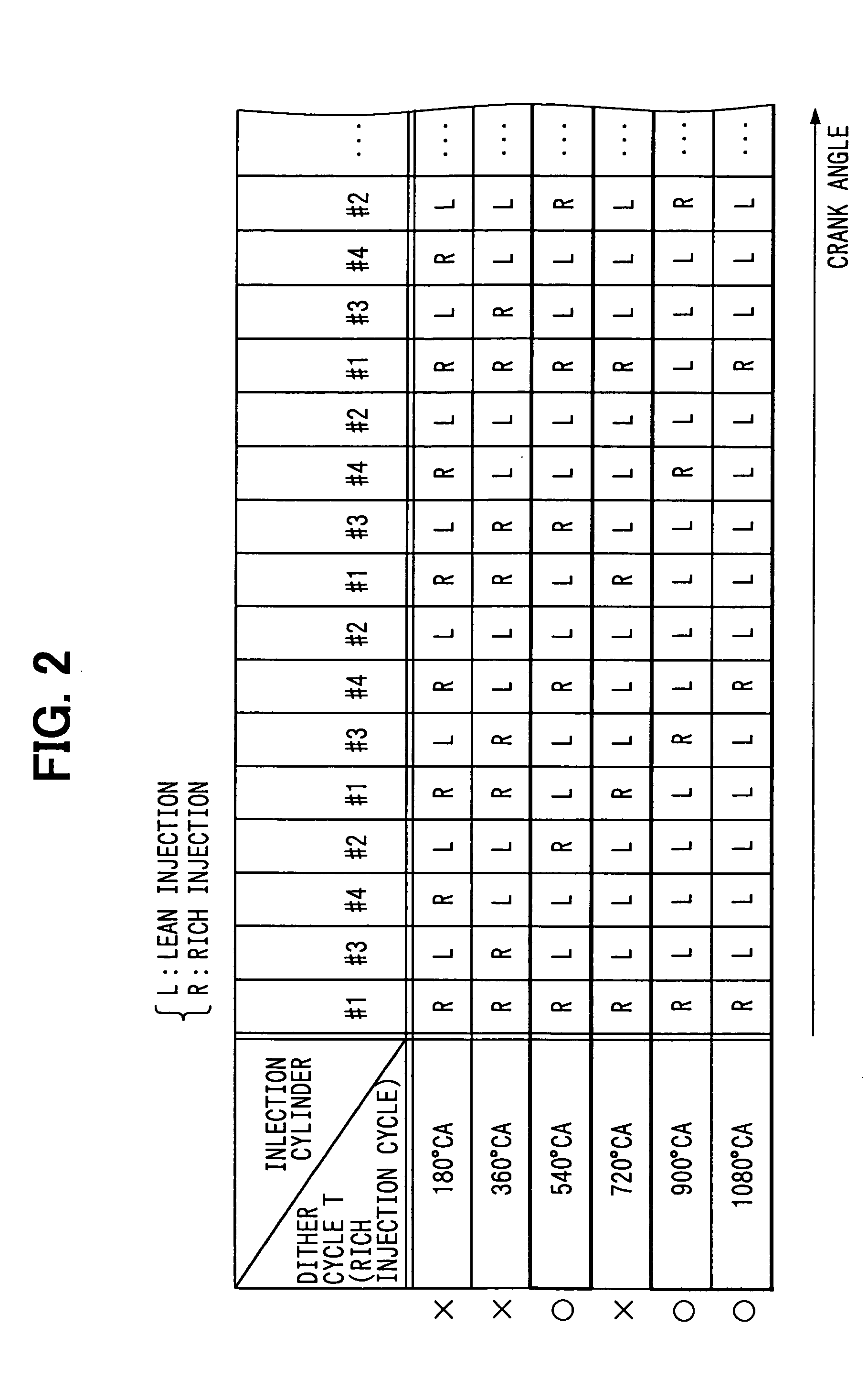
are examples in which the dither cycle T (rich injection cycle) was set to 540.degree. CA, 900.degree. CA, and 1080.degree. CA, respectively, and the irregular injection control was performed such that rich injections did not occur consecutively for the same cylinder. On the other hand, Comparative Example 1 is an example in which the dither cycle T (rich injection cycle) was set to 720.degree. CA and the injection dither control was performed such that rich injections did occur consecutively for the same cylinder. Comparative Example 2 is an example of ordinary lean control in which the lean injection (air-fuel ratio=base air-fuel ratio) was performed for every fuel injection without performing the injection dither control.

[0052] As is obvious from the time chart of FIG. 7, the irregular injection dither control of the Examples 1 to 3, and the injection dither control of Comparative Example 1 are all capable of, by using the injection dither, creating oxidation reaction of the rich...


PUM


Abstract

A rapid catalyst warm-up control device for an internal combustion engine performs irregular injection dither control during the rapid catalyst warm-up control after starting the engine. In the irregular injection dither control, injection modes are switched after every fuel injection to the cylinders (every 180° CA for a 4-cylinder engine) between a lean injection mode and a rich injection mode in such a pattern that rich injections will not occur consecutively for the same cylinder (dither cycle=540° CA, 900° CA, 1080° CA, or the like). In the lean injection mode, fuel is injected such that the air-fuel ratio is leaner than the stoichiometric ratio, and in the rich injection mode, air-fuel ratio is richer than the stoichiometric ratio. The rich gas emitted from the cylinders where the rich injection has been performed is thus allowed to flow through a different catalyst region every time instead of flowing only through the same region.

Description

[0001] This application is based upon, claims the benefit of priority of, and incorporates by reference Japanese Patent Application No. 2003-151933 filed May 29, 2003.[0002] 1. Field of the Invention[0003] The present invention relates to a rapid catalyst warm-up control device for rapidly warming up a catalyst used for purifying exhaust gas from an internal combustion engine.[0004] 2. Description of the Related Art[0005] In recent years, vehicles having an internal combustion engine have been provided with a catalyst such as three way catalyst for purifying exhaust gas from the internal combustion engine. In such systems, since the exhaust gas purification ratio of the catalyst remains low until the catalyst is warmed up to active temperature after starting the engine, measures are taken to rapidly warm up the catalyst. This is done by performing rapid catalyst warm-up control until the catalyst reaches its active temperature after starting up the internal combustion engine.[0006] ...

Claims


Application Information

Patent Timeline
Patent Type & Authority Applications(United States)
IPC IPC(8): F02D41/06F02D41/02F02D41/14
CPCF02D41/0255F02D41/1408Y02T10/26Y02T10/12
Inventor TANAKA, TOSHIHIKOHOSHI, KOICHIITOH, TAKAAKI
Owner DENSO CORP
Why Eureka
Try Eureka