Rim wheel, and tire-rim assembly

Inactive Publication Date: 2004-12-16
BRIDGESTONE CORP
View PDF7 Cites 17 Cited by
  • Summary
  • Abstract
  • Description
  • Claims
  • Application Information

AI Technical Summary

Problems solved by technology

The inventors have studied intensively the known documents described above in which the Helmholtz resonance noise absorber has been applied to a wheel, and they have discovered that, as described below, improvements achieved with this resonator have so far been inadequate, and that problems have been experienced in its practical applications.
In the first place, sufficient benefits cannot be obtained unless a total volume of sub-air chambers used for the Helmholtz resonance noise absorber is sufficiently big in size in relation to a volume of main air chambers of a tire whose level of noise it is intended to be reduced.
However, in practice, it is necessary to obtain a brake space and this makes it difficult to form a large air chamber in the same area.
Further, from the viewpoint of the rigidity of a rim, there is a limit to possible reductions in a plate thickness of a spoke.
However, obtaining a large volume is also difficult.
Although a certain degree of noise reduction can be expected, this is not sufficient to meet the level of reduction desired.
If errors on these factors occur, resonance frequencies deflect from one another, and a sufficient noise reduction cannot be obtained.
However, obtaining dimensional or positional accuracy of sub-air chambers is difficult, and for example, there is a fear that noise reduction may be hampered by variations in lengths of communicating holes.
Furthermore, increases in manufacturing costs, deterioration in productivity and deterioration in a rotational balance can also be disadvantages.
On the other hand, since JP-U No. 1-39103 does not include so-called terms for correcting opening ends in the aforementioned relational expression of the resonance frequency, an appropriate setting cannot be achieved, making it impossible to obtain a sufficient degree of noise reduction.
However, since the rim wheel is formed into a configuration whose diameter is smaller than that of a bead baseline or does not have a so-called rim bottom portion, it is impossible for a tire bead to pass a rim flange, and in practice, rim assembly cannot be carried out.
Consequently, the rim wheel according to this disclosure cannot be put to practical use.
Further, in JP-U No. 1-39103, requirements in respect of the number of air chambers in a circumferential direction of the rim wheel have not been sufficiently studied.
With a single air chamber in an embodiment of this disclosure, improvements are hardly noticeabl

Method used


Image

  • Rim wheel, and tire-rim assembly
  • Rim wheel, and tire-rim assembly
  • Rim wheel, and tire-rim assembly

Examples


example 2

[0246] the number of the diaphragms in Example 1 was changed to three. One communicating hole / air chamber was formed and had a diameter of 1.2 cm.

[0247] Comparative Example 1: the number of the diaphragms in Example 1 was changed to one, and communicating holes were arranged in the same way as in Example 1 (Namely, five communicating holes / air chamber were arranged with an equal distance therebetween in a rim circumferential direction).

[0248] Comparative Example 2: all of the diaphragms in Example 1 were removed and the product had continuous sub-air chambers in a rim circumferential direction. Communicating holes were positioned in the same manner as in Example 1.

[0249] Comparative Example 3: the number of the diaphragms in Example 1 was changed to two. One communicating hole / air chamber was formed and had a diameter of 1.7 cm.

[0250] In accordance with the aforementioned equation, a resonance frequency for each of Examples and Comparative Examples was set to about 250 Hz.

[0251] A ...

example 4

[0269] a diameter of the communicating hole in Example 3 was changed to 1.2 cm, and a resonance frequency was set to about 250 Hz.

[0270] Comparative Example 4: the number of communicating holes in Example 3 was changed to two per one air chamber (holes arranged at a distance of 10 cm from each other at a central portion in a circumferential direction of each sub-air chamber). Each communicating hole had a diameter of 1.1 cm, and a resonance frequency was set to about 330 Hz.

[0271] Comparative Example 5: the number of communicating holes in Example 3 was changed to three per air chamber (holes arranged at distances of 3 cm from each other at a central portion in a circumferential direction of each sub-air chamber). Each communicating hole had a diameter of 1.05 cm, and a resonance frequency was set to about 400 Hz.

[0272] A tire rim assembly using the thus manufactured wheel according to the present invention, and a tire rim assembly using an ordinary control wheel, were respectively...


PUM


Abstract

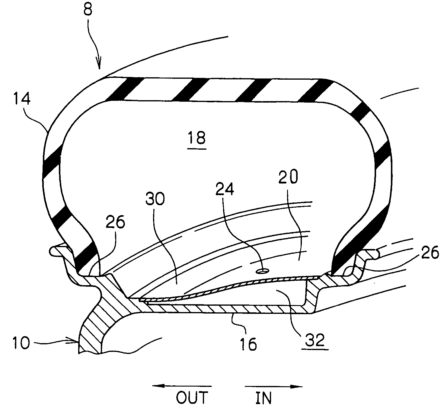
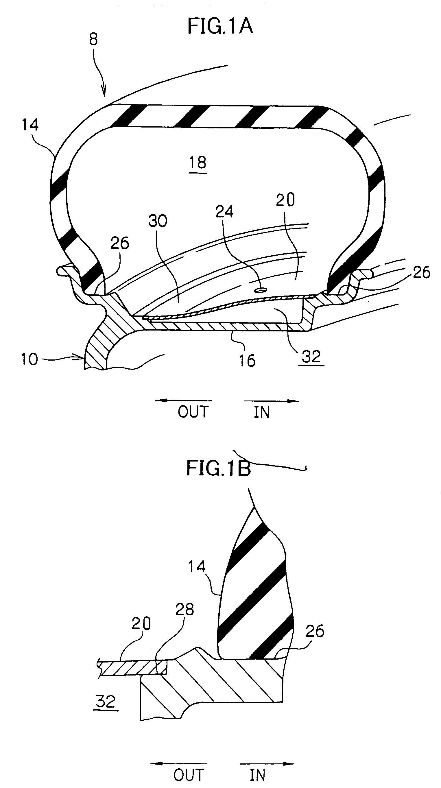
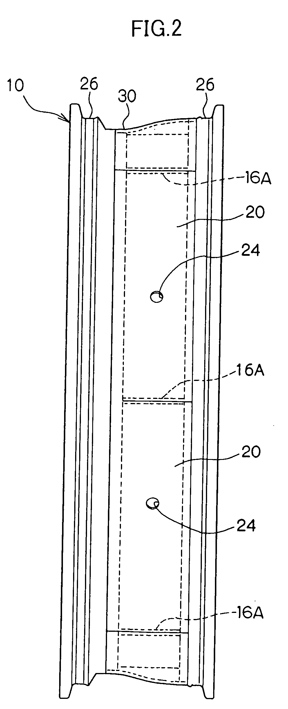
A purpose of the present invention is to provide a rim wheel and a tire rim assembly which are capable of effectively reducing cavity resonance of a tire, and accordingly, enhancing quietness and riding comfort. A plurality of cap members 20 is arranged on an outer circumferential surface of a rim 16 in a circumferential direction thereof, diaphragms are disposed inwardly of each cap member 20, and a plurality of sub-air chambers 32 is formed between the rim 16 and the cap members 20 in a rim circumferential direction. The tire main air chamber 18 is connected to the sub-air chambers 32 through communicating holes 24 formed on the cap members 20. The sub-air chambers 32 and the communicating holes 24 constitute a Helmholtz resonance noise absorber that can absorb vibration with specified frequencies. Further, since the sub-air chamber 32 is not formed in a continuous annular shape in a tire circumferential direction, occurrence of cavity resonance can be suppressed and a substantial reduction in noise can be secured.

Description

[0001] 1. Field of the Invention[0002] The present invention relates to a rim wheel for a vehicle to which a tire is attached, and a tire rim assembly. More particularly, the present invention relates to a rim wheel and a tire rim assembly which can suppress vibration transmitted to a vehicle at the same time as serving high steering stability thus contributing to improve merits in riding comfort, noise reduction inside the vehicle, and the like.[0003] 2. Background Art[0004] In recent years, high functional performances in automobiles are on demand, particularly in the area of luxury automobiles, in which high functional performances good controllability, a high level of riding comfort and quietness are to be excellently secured.[0005] In view of the aforementioned facts, in the so-called "leg vicinity" category including tires, rim wheels and suspensions, improvements has been achieved in technologies for active control of a suspension, rubber for prevention of vibration and the s...

Claims


Application Information

Patent Timeline
IPC IPC(8): B60B21/12B60C17/04B60C19/00
CPCB60B3/02B60B21/023B60B21/12B60C17/04B60C19/00B60C19/002
Inventor MORINAGA, HIROSHIYOKOTA, HIDETOSHI
Owner BRIDGESTONE CORP
Why Eureka
Try Eureka