Manufacturing Method of Fluid Dynamic Pressure Bearing

Active Publication Date: 2005-01-06
NIDEC CORP
View PDF5 Cites 12 Cited by
  • Summary
  • Abstract
  • Description
  • Claims
  • Application Information

AI Technical Summary

Benefits of technology

[0016] In the present invention, gravity may be used for supplying the oil. This can provide a smooth supply of oil. For example, supposing that the density of the oil is about 1 g/cm3, the pressure can be increased by 1000 Pa due to the height difference of 10 cm. Making a suitable height difference enables to supply oil to the second vacuum chamber against the pressure difference between the first vacuum chamber and the second vacuum chamber. Combining the valve m

Problems solved by technology

However, even in the oil filling method as described above, oil often bubbles during filling process.
This is because it is extremely difficult, particularly in a mass production process in a factory, to remove the dissolved air to a degree of not forming air bubbles even by stirring and degassing the oil under the reduced pressure.
The oil bubbling during the oil filling process hinders a smooth supply from the vacuum chamber having the oil stored therein to the bearing-supporting vacuum chamber.
Further, when bubbling occurs at the stage where the oil reaches the bearing-supporting vacuum chamber, th

Method used


Image

  • Manufacturing Method of Fluid Dynamic Pressure Bearing
  • Manufacturing Method of Fluid Dynamic Pressure Bearing
  • Manufacturing Method of Fluid Dynamic Pressure Bearing

Examples


Example

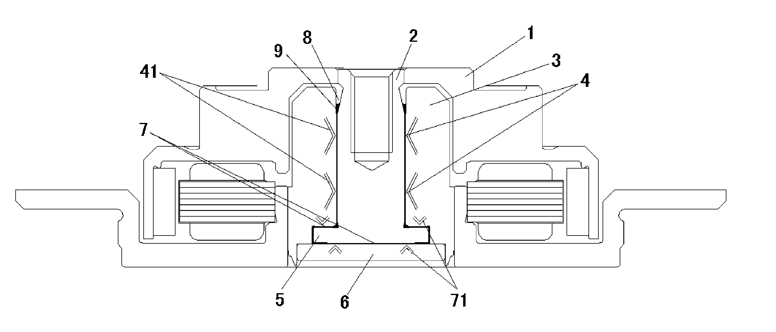
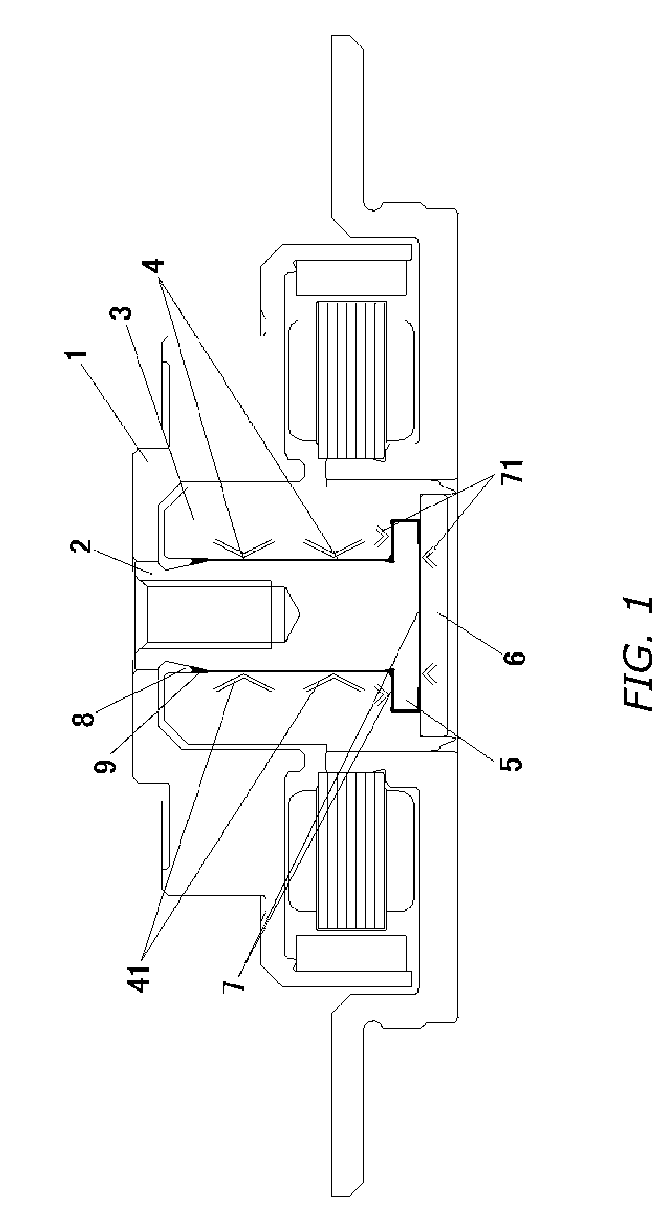
[0020] A manufacturing method of a fluid dynamic pressure bearing device according to an embodiment of the present invention will be explained with reference to drawings. It should be noted that the fluid dynamic pressure bearing 10 is the same as that shown in FIG. 1, so that the explanation of its construction is omitted for avoiding the repeated description.

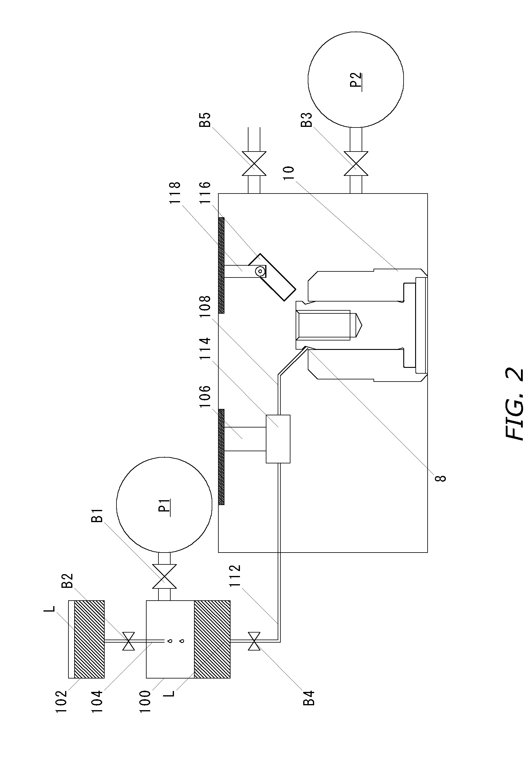
[0021] In the manufacturing method of the fluid dynamic pressure bearing according to the embodiment, a valve B1 is firstly opened and a vacuum pump P1 is operated, whereby air in a first vacuum chamber 100 that is an oil tank is exhausted to be pressure-reduced to a predetermined degree of vacuum PL1. After the reduced pressure level in the first vacuum chamber 100 is confirmed to reach the degree of vacuum PL1, a valve B2 is opened to thereby start a supply of oilL from an oil supplying chamber 102 to the first vacuum chamber 100. At this time, a capillary 104 for supplying the oilL from the oil supplying chamber 102 to the...


PUM

PropertyMeasurementUnit
Pressureaaaaaaaaaa
Pressureaaaaaaaaaa

Abstract

The present invention aims to prevent the occurrence of air bubbles during a filling process of oil or at a stage where a fluid dynamic pressure bearing is incorporated into a motor to be used as a bearing, thereby performing an effective degassing. Upon supplying oil through a pipe that communicates between a first vacuum chamber and a second vacuum chamber upon filling the oil, stored in the first vacuum chamber that is under a reduced pressure environment having a pressure lower than that in the surrounding environment, to the fluid dynamic pressure bearing held in the second vacuum chamber that is similarly under a reduced pressure environment having a pressure lower than that in the surrounding environment, the pressure in the first vacuum chamber is reduced to be lower than the pressure in the second vacuum chamber at the time of filling lubricating fluid.

Description

BACKGROUND OF INVENTION [0001] 1. Field of the Invention [0002] The present invention relates to a manufacturing method of a fluid dynamic pressure bearing used as a bearing device for a spindle motor or the like of a hard disk drive device, and more particularly to an oil filling method into a bearing gap. [0003] 2. Background Art [0004] As a bearing for a motor that requires a high rotational precision such as a spindle motor used in a disk drive device for driving a recording disk such as a hard disk or the like or as a motor for driving a polygon mirror in a laser beam printer, various fluid dynamic pressure bearings have conventionally been proposed that utilize fluid pressure of lubricating fluid such as oil or the like intervened between a shaft and a sleeve for supporting both of them so as to be relatively rotatable. [0005]FIG. 1 shows one example of a motor using such a fluid dynamic pressure bearing. A motor using the conventional fluid dynamic pressure bearing comprises ...

Claims


Application Information

Patent Timeline
IPC IPC(8): F16C33/10B21K1/10C10G21/20F16C17/10F16C32/06F16N31/00F16N37/00
CPCF16C17/107F16C33/103F16C33/107Y10T29/49696Y10T29/49702Y10T29/49639Y10T29/53104
Inventor MISU, ISAOUCHIYAMA, MASAAKI
Owner NIDEC CORP
Why Eureka
Try Eureka