Flow control and operation monitoring system for individual spray nozzles

a technology of operation monitoring and flow control, which is applied in the direction of relative volume flow measurement, road maintenance, and pressurised distribution of liquid fertiliser, etc., can solve the problems of increasing the concern of inefficient agrochemical use, the cost of agrochemicals and inadvertent spray drift or pesticide run-off, and the inability to accurately predict the flow rate of spray nozzles. significant and unavoidable,

Active Publication Date: 2005-01-06
CAPSTAN
View PDF31 Cites 90 Cited by
  • Summary
  • Abstract
  • Description
  • Claims
  • Application Information

AI Technical Summary

Benefits of technology

[0025] In accordance with the present invention, the vibration sensor may sense nozzle vibrations in at least the Z axis direction, the X axis direction, or the Y axis direction. For instance, in one embodiment with a flat fan nozzle, it has been discovered that sensing vibrations in the Z axis provides information regarding the flow rate of a fluid being emitted by the nozzle. Vibrations sensed in the Y axis, on the other hand, may provide information regarding the spray pattern by which the fluid is emitted. When using a fluid nozzle that pulses and emits a fluid according to a duty cycle, vibrations sensed in the X axis may provide information regarding whether the nozzle is pulsating correctly if the orientation of a solenoid valve controlling the pulsation is oriented such that the predominant motion of moving parts of the valve are oriented along the X axis.

Problems solved by technology

Agrochemical manufacturers and regulatory officials are becoming increasingly interested in the spray application process since it affects product efficacy and environmental contamination.
There are increasing concerns over inefficient agrochemical use, the cost of agrochemicals and inadvertent spray drift or pesticide run-off.
Faster ground speeds and wider spray booms can lead to application errors that are significant yet unavoidable with existing spray technology.
Unless the flow rate from each nozzle is individually adjusted to compensate for these differences in travel speeds, application errors may occur.
Currently, the maximum resolution (smallest area that can get a distinct rate) for most products is limited by the width of the spray boom.
Rate controllers usually control the entire boom as a unit and do not allow different boom sections, let alone individual nozzles, to discharge different rates.
Some increase in spatial resolution of variable rate application can be achieved by individual control of distinct boom sections using existing technology but the systems can involve cumbersome plumbing, wiring and operator interfaces.
Since the operator is unlikely to stop the vehicle and leave the cab between refillings, clogged nozzles or other problems on the boom are unlikely to be detected while significant land areas are being treated.
Additionally, the wider boom widths, travel speeds and vehicle sizes increasingly restrict an operator's view of the boom and the opportunities to view the boom while driving.
A similar problem exists on shielded or shrouded sprayers sometimes used in the North American Plains and in urban and landscape applications.
In farming areas in extreme southern and northern latitudes and in high value specialty crops, often grown in coastal areas, the agronomic time window for pesticide applications can be critically short and often occurs during windy periods.
Improperly operating nozzles are not easily detected.
While effective, this requires cumbersome plumbing for each nozzle and that the operator visually monitor the bank of tubes.
It should be noted that relying on visual inspection (either direct line of sight or video) or simple flow measurement (ball in tube) does not assure proper nozzle operation.
Nozzles can be partially clogged or have an obstruction in the flow path and appear to be operating correctly even if the flow rate is significantly affected.
Conversely, the nozzle pattern and spray droplet size can be severely distorted by an obstruction or damage, yet the flow rate remains close to the original value.
Even with the electronic control or monitor system, the driver would likely remain unaware of the failure.
The opportunity for failure is increased over that of a simple nozzle.
For example, on irrigation systems, there may be many small nozzles, often obscured from view or in areas that are difficult to access.
Failure of a nozzle might not be detected until drought damage to a plant had occurred and symptoms were visible.
Likewise, in industrial spray driers, malfunction of a nozzle might not be detected until significant amounts of product had been damaged.
In a spray humidification or cooling systems, nozzle failures might not be detected until excessive heating or drying had occurred.

Method used


Image

  • Flow control and operation monitoring system for individual spray nozzles
  • Flow control and operation monitoring system for individual spray nozzles
  • Flow control and operation monitoring system for individual spray nozzles

Examples


example no.1

EXAMPLE NO. 1

[0056] Characteristic vibration of the spray atomization process was investigated using a single nozzle test stand, a multiple nozzle test stand and a commercial, self-propelled field sprayer (Case 4260, CNH Global). The single nozzle test stand used air pressured canisters for liquid flow; this eliminated any vibration from pumps and bypass flow in the system. The multiple (3) nozzle test stand used an electric vane pump and allowed various configurations of pulsing flow to be generated. Data from the multiple (3) nozzle test stand were compared to the single nozzle stand. Pump and pipe flow vibrations were not found to affect the nozzle vibration measurements.

[0057] The primary instrument for data collection in these examples was an ICP triaxial accelerometer (PCB Model 356A22) with frequency response of 0.4 Hz to 6 kHz, 0.4 to 10 kHz (sensitive) and nominal output of 100 mV / g. The accelerometer was rigidly coupled to the nozzle cap using a 5-40 machine screw stud. R...

example no.2

EXAMPLE NO. 2

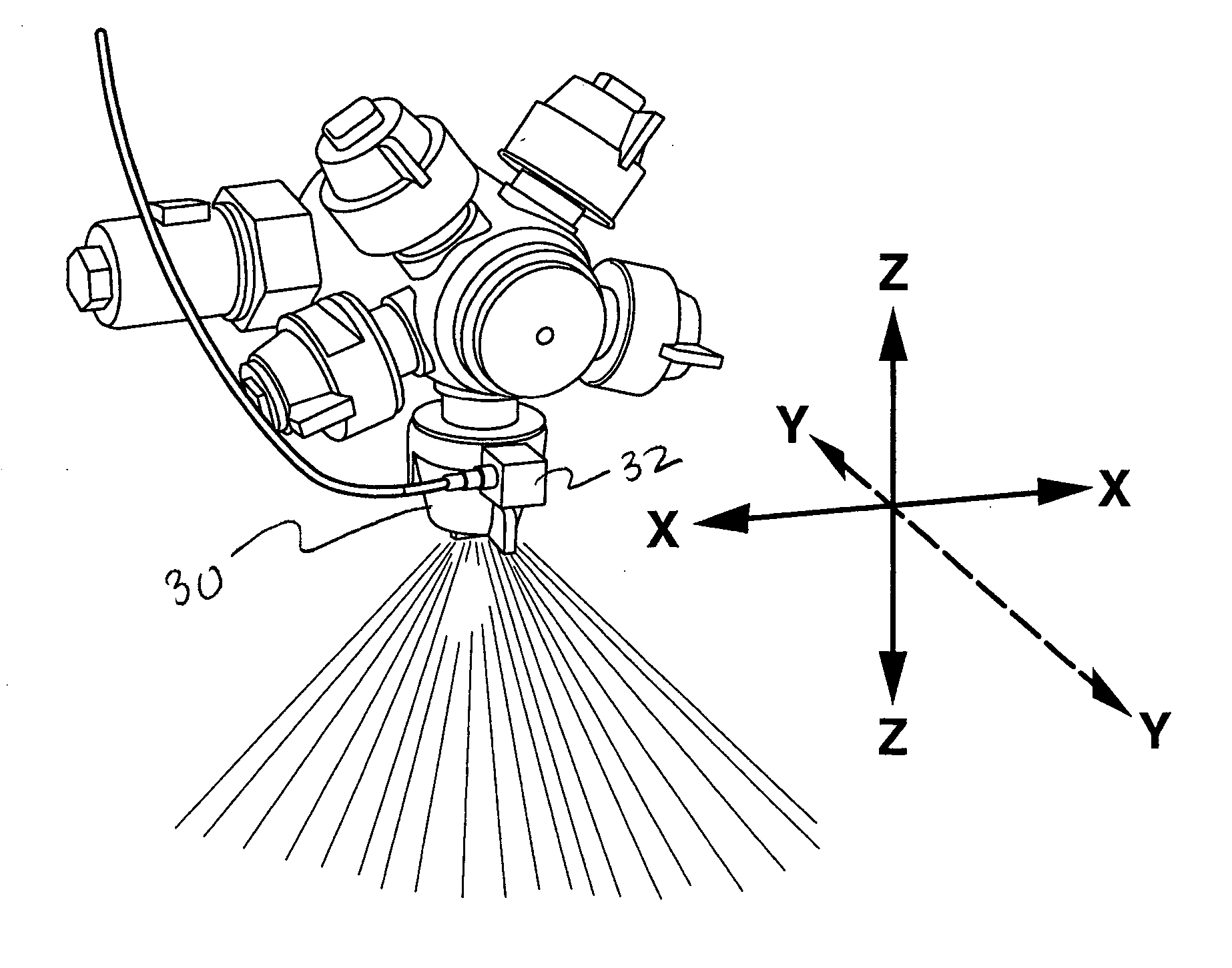
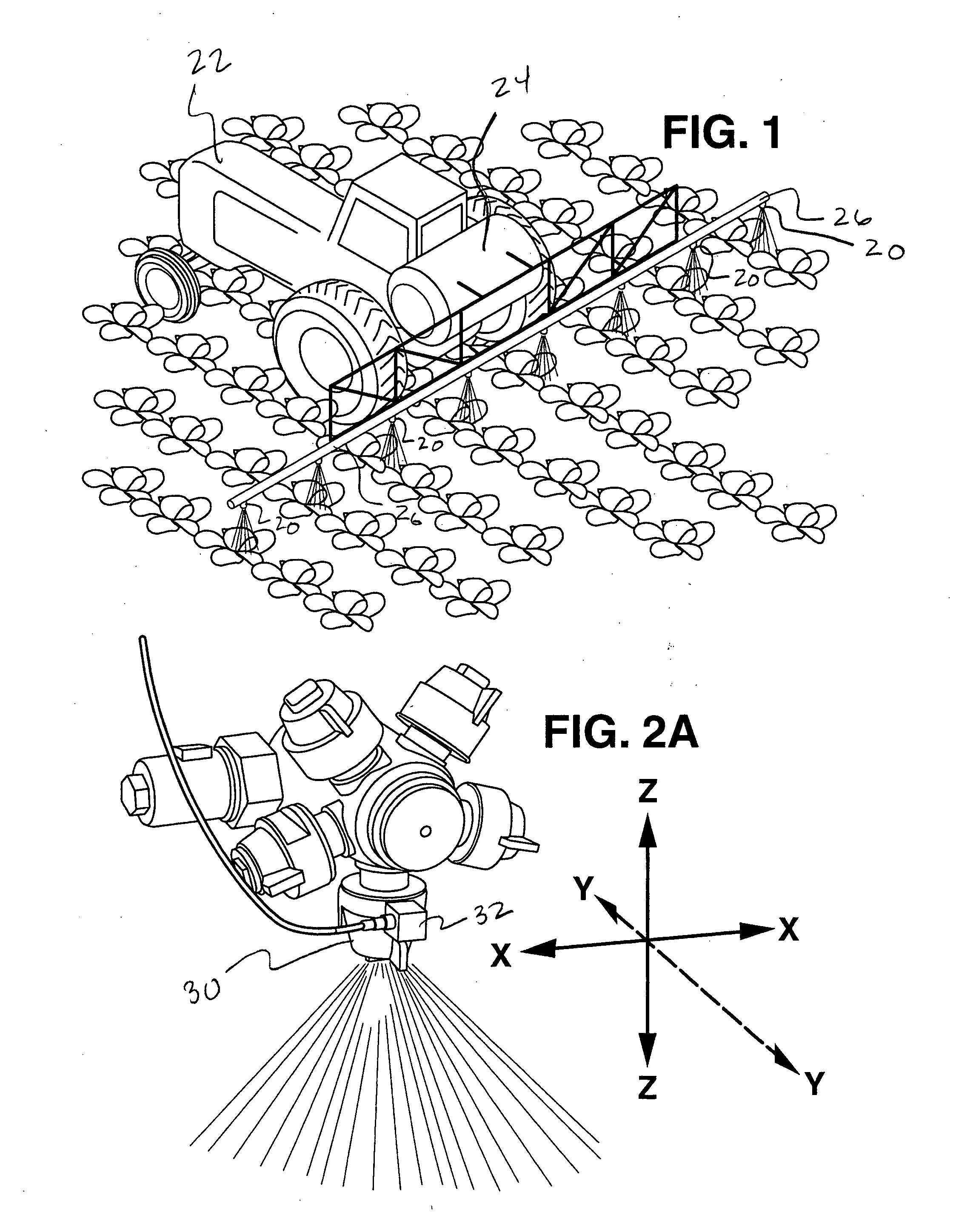
[0078] The normal and clogged nozzle tests described above addressed study of continuous spray flow. The next set of experiments addressed the measurement of pulsing flow sprays. The configuration shown in FIG. 2 was used for testing. A standard Capstan Agricultural Systems, Inc. Synchro® 12 Vdc, 7 W, direct-acting electrical solenoid valve was installed in place of the standard diaphragm check valve on the nozzle body assembly. The valve was actuated at with a square wave electrical signal at 15 Hz and a 60% duty cycle using a commercial Capstan Sharpshooter® electronic system. The asymmetry of the 60% duty cycle allowed the on and off times to be easily distinguished in data plots. During all testing, the valves on the nozzles adjacent to the test nozzle were actuated at the same frequency and duty cycle but 180° out of phase; this is identical to how the Capstan blended pulse liquid spray products are configured on field machines. Adjacent nozzle bodies were installe...

example no.3

EXAMPLE NO. 3

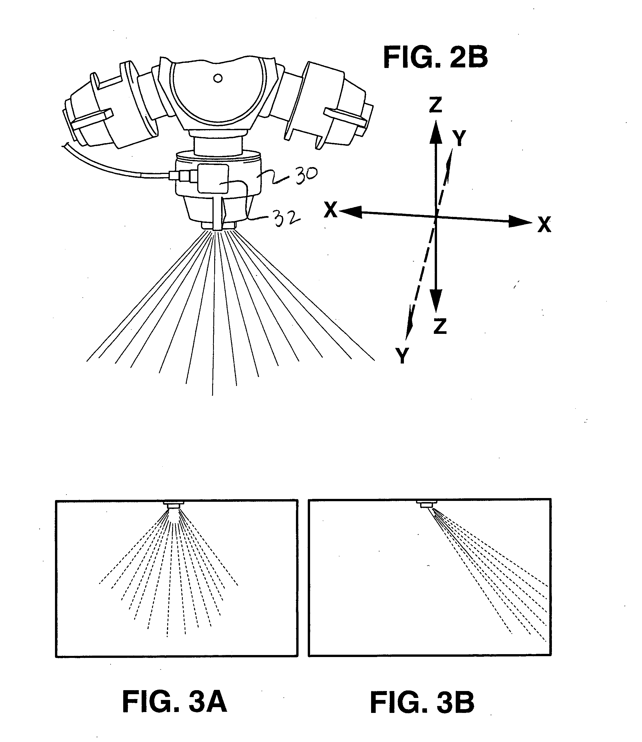
[0082] To demonstrate the feasibility of the present invention on an actual field sprayer, the triaxial accelerometer described above was mounted on a nozzle body on the boom of a Case 4260 self propelled sprayer with a 25 m, 54 nozzle boom and an AIM Command® pulsed flow control system. For instance, referring to FIGS. 9 and 10, the nozzle 30 is shown mounted on a spray boom 34. As also illustrated, the vibration sensor 32 is mounted onto the nozzle 30.

[0083] The system was operated at full engine throttle (2300 rpm), full pump flow for spray and agitation and with all valves (except the test location with the various nozzles installed) pulsing with 11010 nozzles (110° spray angle at 1.0 gal / min). As is done in the commercial product, alternate valves were pulsed ½ period (180°) out of phase. The field test represented a situation very close to actual spraying conditions.

[0084] Time data is shown for the X—, Y—, and Z-axis in FIGS. 11A through 11C for the system with...


PUM


Abstract

An apparatus and process for monitoring fluid flow through a nozzle is disclosed. A vibration sensor, such as an accelerometer, is mounted to a nozzle. The vibration output received from the sensor is then analyzed to determine whether or not the nozzle is operating properly. Through the present invention, information can be obtained regarding variations in flow rate, and / or variations in spray pattern and droplet size spectra. If the nozzle flow pulsates, the vibration sensor may also provide information regarding whether the nozzle is pulsating according to a desired frequency duty cycle or waveform.

Description

RELATED APPLICATIONS [0001] The present application is based on and claims priority to a provisional application filed on Mar. 10, 2003 and having U.S. Application No. 60 / 453,388.BACKGROUND OF THE INVENTION [0002] Most agrochemicals such as crop protection agents and many fertilizers are applied as liquid solutions, suspensions and emulsions that are sprayed onto the target fields. Conventional spray technology is well known and generally understood by farmers, equipment manufacturers and extension agents. Agrochemical manufacturers and regulatory officials are becoming increasingly interested in the spray application process since it affects product efficacy and environmental contamination. Typically, the agrochemical liquid is supplied by powered pumps to simple or complex orifice nozzles that atomize the liquid stream into spray droplets. Nozzles are often selected primarily on the desired range of flow rates needed for the job and secondarily on the range of liquid droplet size ...

Claims


Application Information

Patent Timeline
Patent Type & Authority Applications(United States)
IPC IPC(8): A01C23/04A01M7/00B05B12/00B05B12/08B05B15/02
CPCA01C23/047A01M7/0089B05B15/02B05B12/004B05B12/082A01M7/0096B05B15/50
Inventor GILES, DURHAM KENIMER
Owner CAPSTAN
Why Eureka
Try Eureka