Acceleration sensor

a technology of acceleration sensor and acceleration sensor, which is applied in the direction of rapid change measurement, instruments, measurement devices, etc., can solve the problems of deteriorating the accuracy of acceleration sensor, difficulty in automatically assembling acceleration sensor, and rise in the production cost of acceleration sensor b>100/b>, and achieves the effect of simple construction

Inactive Publication Date: 2005-01-06
PANASONIC CORP
View PDF10 Cites 6 Cited by
  • Summary
  • Abstract
  • Description
  • Claims
  • Application Information

AI Technical Summary

Benefits of technology

It is therefore a primary object of the present invention to provide an acceleration sensor

Problems solved by technology

As will be seen from the forgoing description, the first conventional acceleration sensor 100, however, encounters such problems that it is difficult to automatically assemble the acceleration sensor 100 resulting from the fact that one of the electrodes 104 of the piezoelectric element 103 is required to be electrically connected with the output terminal 107 of the cover member 106 through the wire 105 having both ends soldered with them, respectively, by way of, for instance, wire bonding.
This leads to the fact that the production cost of the acceleration sensor 100 rises.
The uneven oscillation of the oscillation plate causes the piezoelectric element to generate a noise output voltage and deteriorate the accuracy of the acceleration sensor.
This leads to the fact that the oscillation of the oscillation plate at a frequency in

Method used


Image

  • Acceleration sensor
  • Acceleration sensor
  • Acceleration sensor

Examples


first embodiment

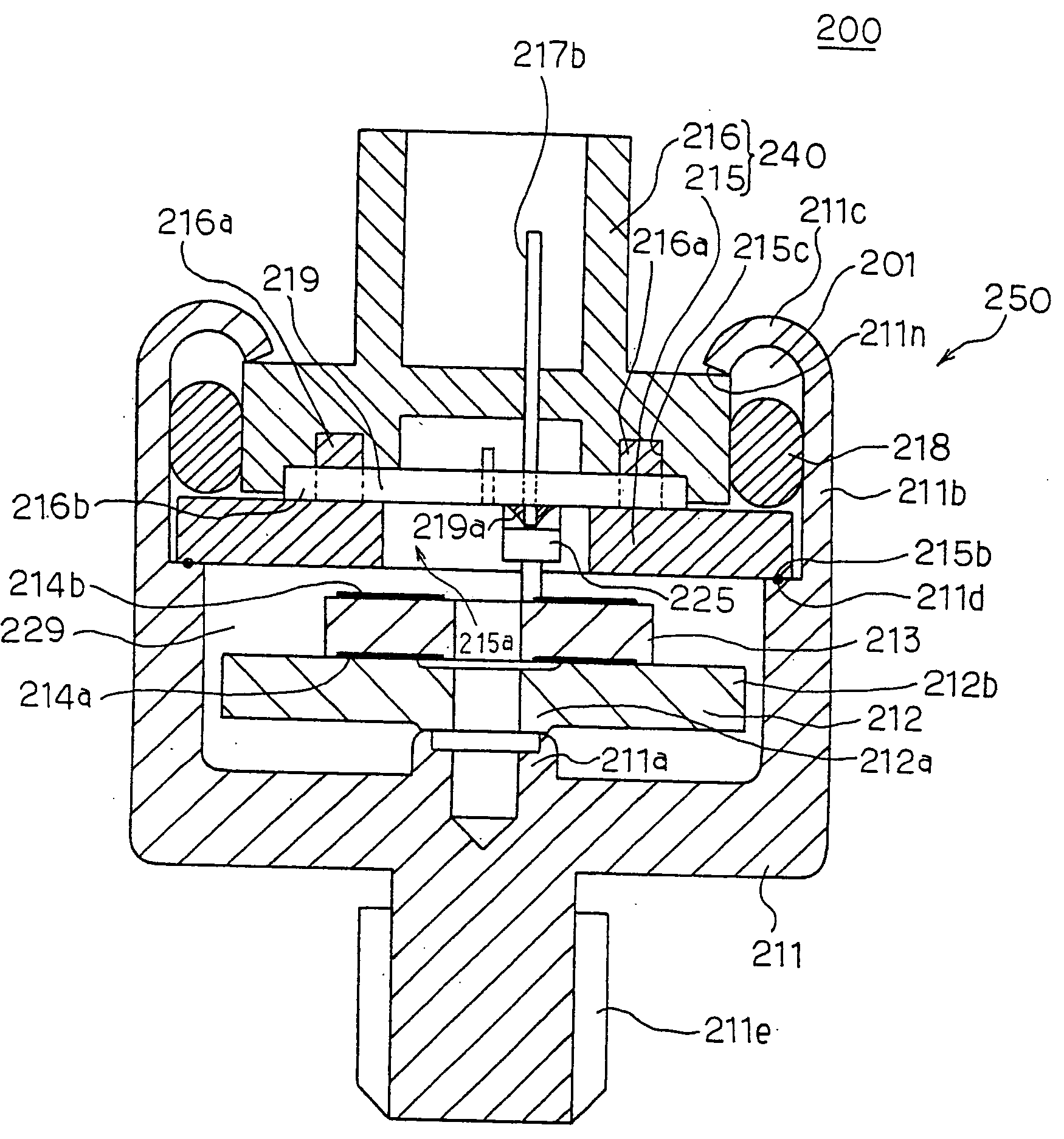
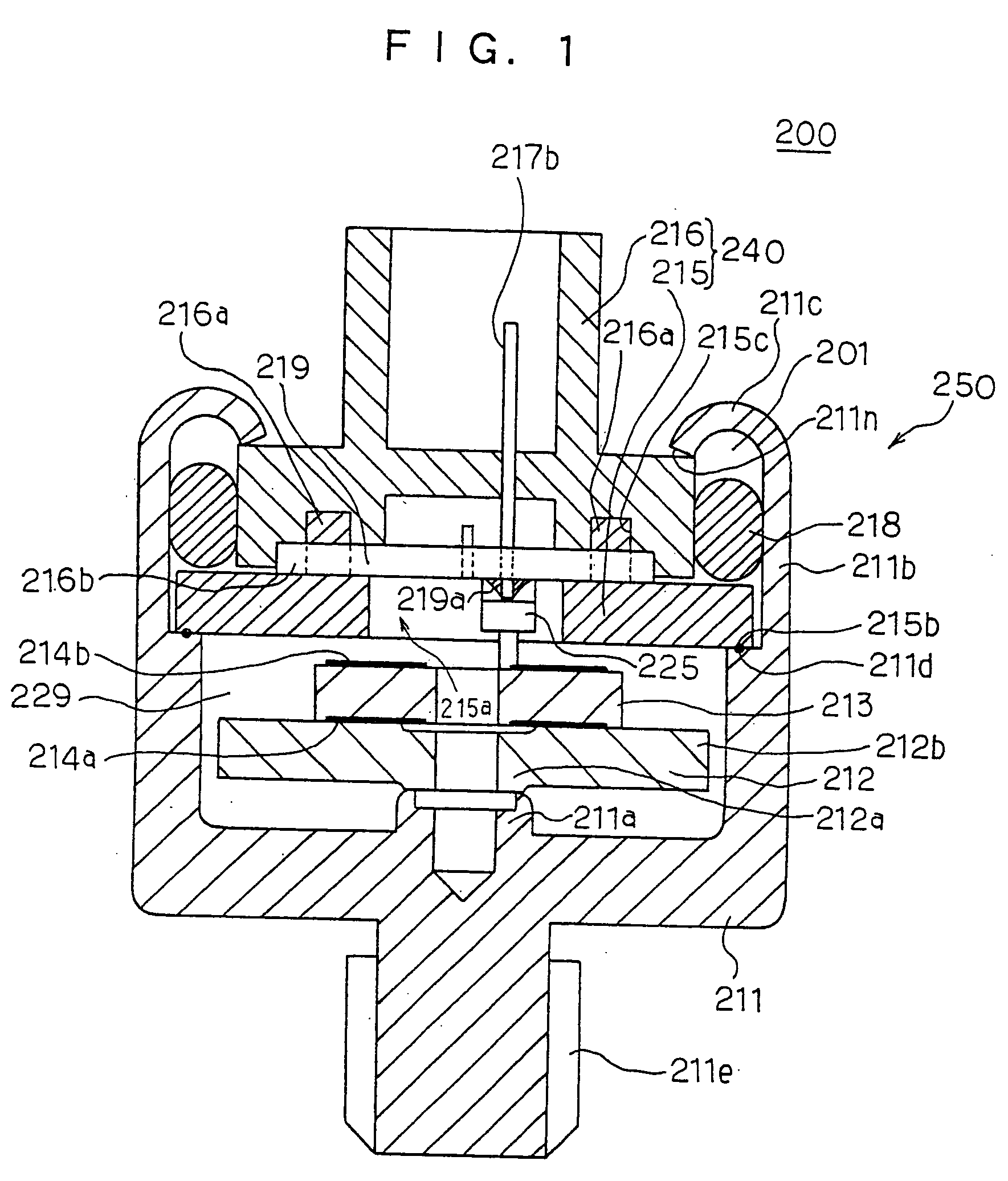
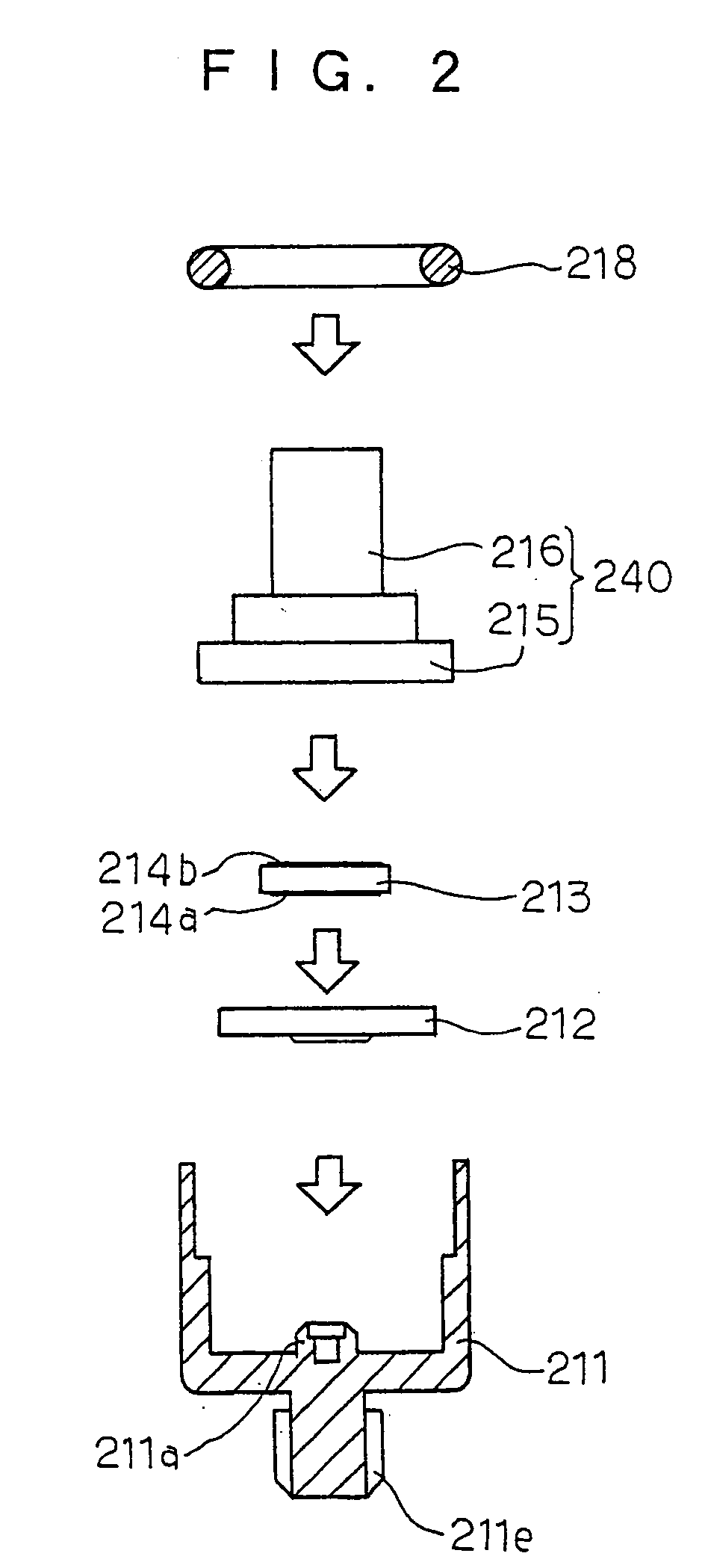
the acceleration sensor 200 further comprises an oscillation plate 212 with the central portion 212a securely supported similar to the first and second conventional acceleration sensors 100 and 110 and designed to have a resonance frequency f0 of the oscillation plate 212 out of the predetermined range of effective oscillation frequencies actually used for detecting an acceleration so that the flat portion V0 of the output voltage range is used for detecting an acceleration (see FIG. 28).

The acceleration sensor 200 further comprises a terminal pin 217b extending through the cover assembly 240 and terminating at the exterior of the cover assembly 240, and a printed board 219 retained by the cover assembly 240 to have the second electrode 214b of the piezoelectric element 213 and the terminal pin 217b connected with each other. This leads to the fact that the terminal pin 217b serves as an output terminal. The printed board 219 has a copper plated pattern 219a on one or both surfaces...

third embodiment

the acceleration sensor 300 can be modified as a fourth embodiment of the acceleration sensor 300 in a manner that that the dimensions of the oscillation plate 312, the piezoelectric element 313 and the supporting portion 311a of the fixed case member 311 are modified. The fourth embodiment of the acceleration sensor 300 as a modification of the third embodiment of the acceleration sensor 300 will be described hereinafter. The constitutional elements and parts of the fourth embodiment of the acceleration sensor 300 same as those of the third embodiment of the acceleration sensor 300 are simply represented by the same reference numerals as those of the third embodiment of the acceleration sensor 300, and will be thus omitted from description for avoiding tedious repetition.

Referring to FIGS. 4 to 5 of the drawings, there is shown a fourth preferred embodiment of the acceleration sensor 300 according to the present invention.

In the fourth embodiment of the acceleration sensor 300, ...

fourth embodiment

the acceleration sensor 300 thus constructed can enhance both the resonance frequency f0 and the sensitivity V0, thereby making it possible to improve the performance of the acceleration sensor 300.

The fourth embodiment of the acceleration sensor 300 has, however, a drawback that the adhesive area between the piezoelectric element 313 and the oscillation plate 312 is curtailed, thereby causing the adhesive strength between the piezoelectric element 313 and the oscillation plate 312 to be unevenly distributed and weakened.

The foregoing third and fourth embodiments of the acceleration sensor 300 can be replaced by a fifth embodiment of the acceleration sensor 300 in order to improve the performance of the acceleration sensor 300.

The third and fourth embodiments of the acceleration sensor 300 can be modified as a fifth embodiment of the acceleration sensor 300 in a manner that that the dimensions of the oscillation plate 312, the piezoelectric element 313 and the supporting portio...


PUM


Abstract

An accleration sensor comprises a fixed case member and a cover assembly collectively defining a closed space in which the oscillation plate and the piezoelectric element received therein. The oscillation plate and the piezoelectric element are oscillatably supported by a supporting portion formed on the central bottom portion of the fixed case member. The oscillation plate and the piezoelectric element are integrally oscillatable in two different modes consisting of: a 1/1 oscillation mode where the oscillation plate is irregularly deformed to have the peripheral portion oscillated with a single vector in the oscillation direction of the oscillation plate when the oscillation plate is oscillated with respect to the fixed case member at a resonance frequency f0; and a 1/2 oscillation mode where the oscillation plate is irregularly deformed to have two different half parts of the peripheral portion oscillated with their respective different vectors opposite to each other in the oscillation direction of the oscillation plate when the oscillation plate is oscillated with respect to the fixed case member at a noise frequency f01, and the resonance frequency f0 and the noise frequency f01 are out of the range of effective oscillation frequencies. Thus constructed acceleration sensor is of high performance and appropriate for automatic production at a low cost.

Description

BACKGROUND OF THE INVENTION 1. Field of the Invention The present invention relates to an acceleration sensor, and more particularly to an acceleration sensor for detecting an acceleration by transforming oscillation levels into electrical signals. 2. Description of the Related Art In general, the acceleration sensor now in use includes various types such as an electro magnetic type, a piezoelectric element type, and a semiconductor type which are known as detecting an acceleration applied thereto. Among these types of acceleration sensor, the piezoelectric element type of the acceleration sensor has a piezoelectric element deformable in response to the acceleration to detect the acceleration. These piezoelectric element types of the acceleration sensor are applied to automotive vehicles and used for controlling knocking of engine and air bag. A conventional piezoelectric element type of the acceleration sensor herein raised for example is shown in FIG. 25 to comprise an oscill...

Claims


Application Information

Patent Timeline
IPC IPC(8): G01L23/22G01P1/02G01P15/09
CPCG01L23/222G01P15/0922G01P1/023
Inventor BABA, HIROYUKIMATSUMOTO, HIDEKI
Owner PANASONIC CORP
Why Eureka
Try Eureka