Mixing arrangement for atomizing nozzle in multi-phase flow

a technology of atomizing nozzle and mixing arrangement, which is applied in the direction of charging-discharging device combination, combustion type, lighting and heating apparatus, etc., can solve the problems of significant degradation of atomization efficiency, achieve easy processing, improve flow characteristics, and smoke-free bitumen transition

Active Publication Date: 2005-01-06
NAT RES COUNCIL OF CANADA +1
View PDF20 Cites 194 Cited by
  • Summary
  • Abstract
  • Description
  • Claims
  • Application Information

AI Technical Summary

Benefits of technology

[0005] The present invention is intended to overcome the problems associated with the mixing arrangement of the above-identified U.S. patent. This is achieved through re-aligning the bitumen and steam conduits so that they meet the main conduit at acute angles with respect thereto and by removing the flow-accelerating nozzle from the main conduit. There is a smoother transition of bitumen and steam as these products pass from their respective conduits into the main conduit. Also, with the present invention the flow-accelerating nozzle is moved to the steam conduit and is located therein close to the point at which that conduit meets the main conduit, such that the steam is already accelerating as it enters the main conduit rather than after entering as with the prior art. There is a dramatic improvement in flow characteristics with the mixing arrangement of the present invention as compared to the prior art and the resultant atomized bitumen that enters the reactor is more easily processed into appropriate petroleum products than with the apparatus of the prior art.
[0006] The present invention, like the prior art, utilizes the formation of small bubbles of gas (steam) to carry the liquid phase (bitumen) to the atomizing nozzle. The present invention will enhance the formation of bubbles in such multi- or 2-phase flow. Specifically, with the arrangement of the present invention there is enhance formation of bubbles less than 2 mm in diameter that are evenly distributed within the flow downstream of the point at which the gas and liquid phases are mixed. By providing a “bubbly flow” with this arrangement, the liquid is dispersed and is more easily atomized than with other types of 2-phase flow, such a slug or annular flow. The bubbles of gas in the liquid enhance downstream atomization through the exit orifice by the nature of the gas phase compressibility. By producing a uniform distribution of fine bubbles in the flow, the liquid is broken down into small webbed or ligament structures that are more easily broken into droplets when the gas decompresses at the nozzle exit. The uniformity of bubble distribution within the liquid ensures a near constant (with respect to time) gas-to-liquid mass ratio thereby giving consistent atomization (or droplet size). The flow has a minimal pulsing in it, thereby minimizing variations in the atomization over any period of time. This is in contrast to other designs of 2-phase flow mixing devices that may or may not produce a bubbly flow. For example, if there is a slug type flow, a large variation (with time) of the gas-to-liquid mass ration at the nozzle tip can result, causing significant degradation in atomization efficiency.
[0007] It may be noted that the present invention was developed for applications in which a low gas-to-liquid mass ratio is used, to minimize costs for compressible gas phase use. Typically, the present invention works well for gas-to-liquid (GLR) mass ratios of 0.5% or higher. In actual tests, the GLR has been used as high as 1.5% without encountering a change to slug flow.

Problems solved by technology

For example, if there is a slug type flow, a large variation (with time) of the gas-to-liquid mass ration at the nozzle tip can result, causing significant degradation in atomization efficiency.

Method used


Image

  • Mixing arrangement for atomizing nozzle in multi-phase flow
  • Mixing arrangement for atomizing nozzle in multi-phase flow
  • Mixing arrangement for atomizing nozzle in multi-phase flow

Examples


Embodiment Construction

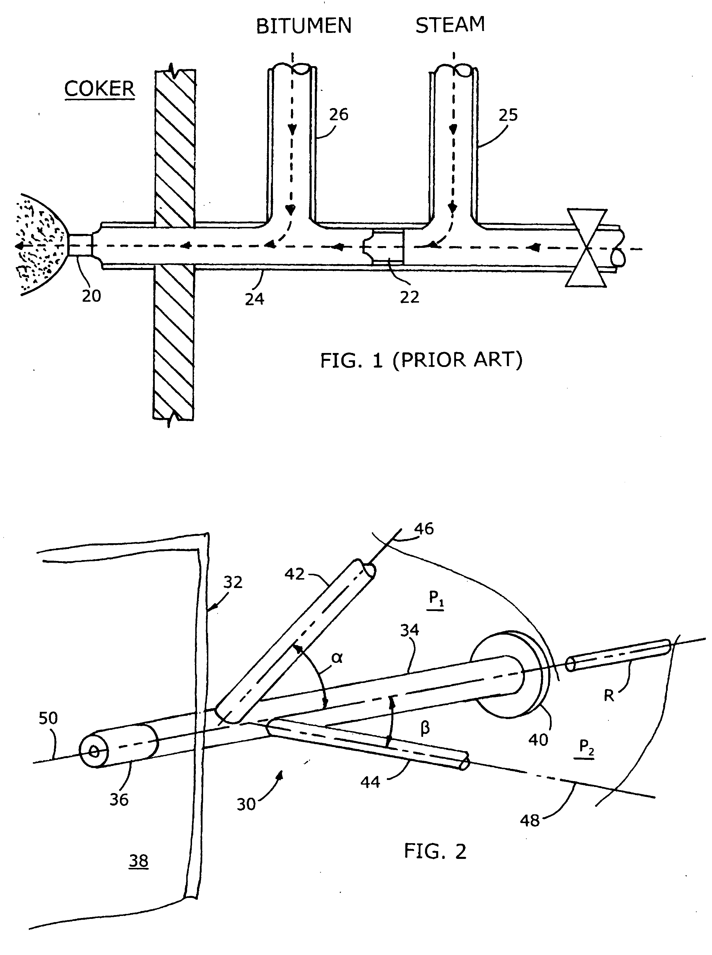
[0015]FIG. 1 as discussed above illustrates a prior art mixing arrangement in which both the bitumen and steam conduits (26, 25) meet the main conduit 24 at right angles, the bitumen and steam conduits being generally parallel to each other.

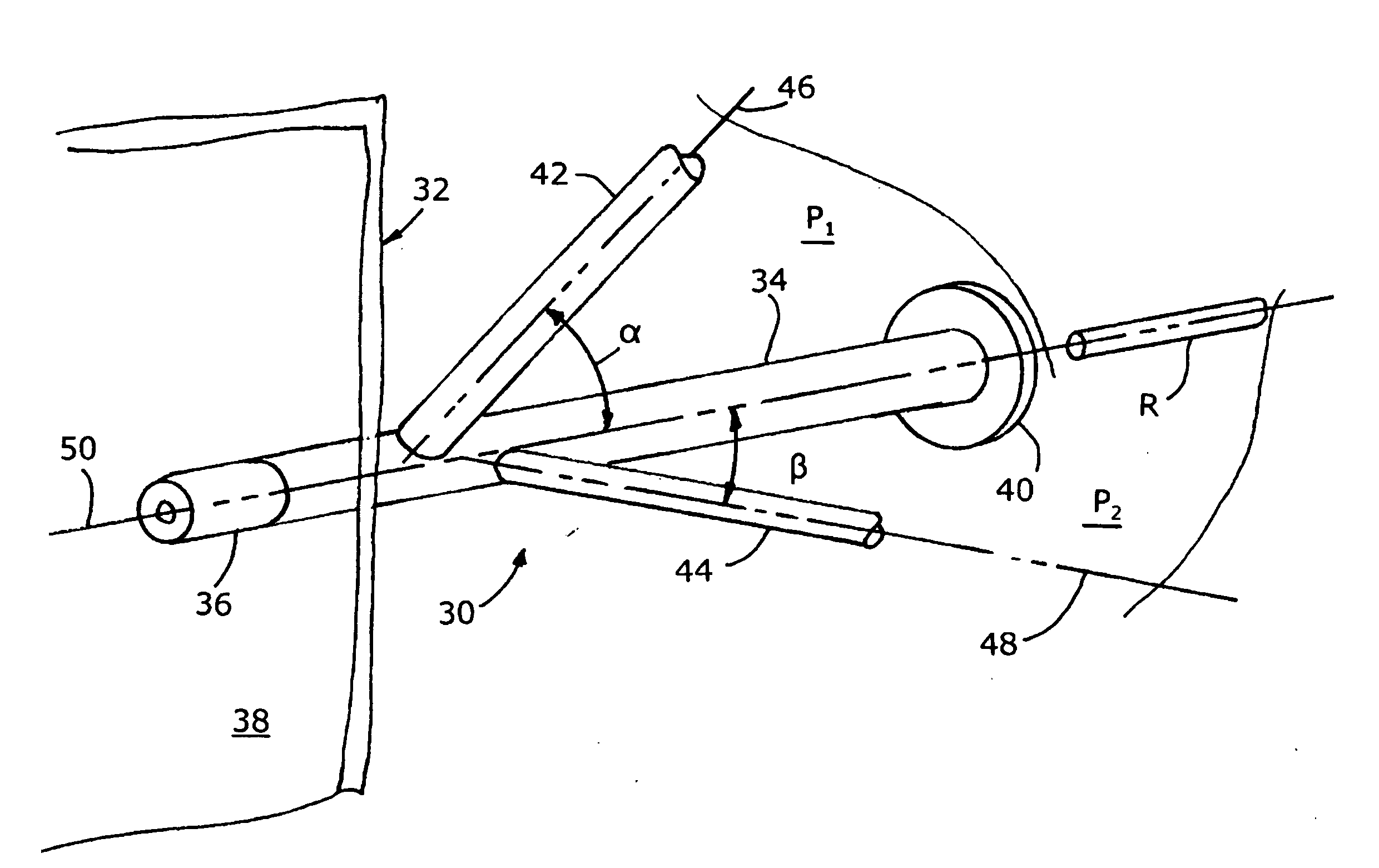
[0016]FIG. 2 illustrates a mixing arrangement 30 in accordance with the present invention, as utilized with a reactor or coker 32. The mixing arrangement of this invention includes a main conduit 34 connected at a proximal end thereof to an atomizing nozzle 36 that is fixed in a wall 38 of the reactor. The atomizing nozzle 36 does not form a part of the present invention and can be one similar to the one disclosed in the aforementioned U.S. Pat. No. 6,003,789. At the distal end of the conduit 34 is a valve or closure member 40 which can be opened to admit a cleaning rod R, used to push any bitumen that might be clogging the conduit 34 through the conduit and the atomizing nozzle into the reactor. Normally the closure member 40 will be closed dur...


PUM

PropertyMeasurementUnit
angleaaaaaaaaaa
angleaaaaaaaaaa
angleaaaaaaaaaa

Abstract

The invention relates to an improved mixing arrangement for, primarily, moving bitumen in steam from sources of such bitumen and steam to a reactor or coker for further processing of the bitumen into petroleum products. The invention provides a main conduit connected to an atomizing nozzle mounted in a wall of the reactor and first and second conduits for flowing bitumen and steam respectively into the main conduit. The first conduit is angled relative to the main conduit at an acute angle of about 45° and the second conduit is angled relative to the main conduit at an acute angle of about 30°. The second conduit is positioned downstream of the first conduit by a short distance of about 23 mm and may be angled radially relative to the first conduit by any angle, although a 90° angle is preferred. A flow accelerating nozzle is located in the second conduit adjacent the entrance therefrom into the main conduit. The arrangement of the invention improves the flow characteristics of 2-phase material flowing to the atomizing nozzle, reducing pulsations in the main conduit and improving the resulting atomization of the bitumen in the reactor.

Description

[0001] The present invention relates to a mixing assembly for an atomizing nozzle used in multi-phase flow and in particular to such an assembly that would be used with oil or bitumen and steam being fed to a coker. BACKGROUND OF THE INVENTION [0002] When bitumen or heavy oil is extracted from tar sands it is not initially in condition for further processing into usable petroleum products. Usually the bitumen is processed in a reactor or a coker, in which atomized droplets of the bitumen in a carrier such as steam are heated to produce low-boiling petroleum products. The efficiency of the coking process is enhanced if the bitumen droplets are of a uniform small diameter, of the order of 300 μm. In a typical installation the bitumen is introduced into a flowing stream of high pressure steam and preferably is broken down into bubbles or particles as the 2-phase mixture of bitumen and steam flows along a mixing apparatus which then pass through an atomizing nozzle into the interior of ...

Claims


Application Information

Patent Timeline
Patent Type & Authority Applications(United States)
IPC IPC(8): B01F5/02B01J19/26B03B9/02C10B55/00
CPCB01F5/0256B01F2215/0422C10B55/00B01J19/26B01F2215/0481B01F25/23
Inventor MCCRACKEN, THOMAS WILLIAMBENNETT, ADAM J.JONASSON, KEVIN A.KIRPALANI, DEEPAKTAFRESHI, ZAHRABASE, TERRENCE B.BASE, IRENEEMBERLEY, DOUGLAS A.KENNETT, R. DOUGLASBULBUC, DANIEL J.CHAN, EDWARD W.
Owner NAT RES COUNCIL OF CANADA
Why Eureka
Try Eureka