Stand for liquid crystal television and stand for liquid crystal display

a technology of liquid crystal television and stand, which is applied in the direction of television systems, electrical apparatus casings/cabinets/drawers, instruments, etc., can solve the problems of difficult to adjust the inclination to one, needing a large installation space, etc., and achieves the effect of smooth movement, increased push force of the abutment member on the side of the slider

Inactive Publication Date: 2005-01-06
FUNAI ELECTRIC CO LTD
View PDF7 Cites 40 Cited by
  • Summary
  • Abstract
  • Description
  • Claims
  • Application Information

AI Technical Summary

Benefits of technology

[0020] With the stand for liquid crystal display in the first aspect, by making the side center portion of the slider substantially flat and providing the movement restricting member that pushes the substantially flat side center portion with a predetermined push force and restricts movements of the slider caused at a force equal to or less than a predetermined moving force in the manner described above, the stand member mounted on the slider can be prevented from moving due to the dead weight of the liquid crystal television, and when an angle of the stand member is to be adjusted, the slider can be moved by application of a force equal to or larger than a predetermined moving force while a push force of the movement restricting member against the substantially flat side center portion of the slider is maintained constant. Also, by forming the side center portion of the slider to make the same substantially flat, the side center portion of the slider is made free of any step, so that the slider can be moved continuously in a stepless manner. Thereby, the stand member connected to the slider can be extended or contracted continuously in a stepless manner in a range, in which the substantially flat side center portion of the slider abuts against the movement restricting member. Thereby, a length of the stand member can be adjusted steplessly relative to the holding member in a range, in which the substantially flat side center portion of the slider abuts against the movement restricting member, so that an inclination of the liquid crystal television can be adjusted to an optional angle in a predetermined angular range. Also, an inclination of the liquid crystal television can be adjusted by extending and contracting the stand member, so that it is possible to adjust an inclination of the liquid crystal television without shifting a position of the liquid crystal television and a position of the support of the stand member relative to a rest surface. Thereby, a distance between a position, in which the liquid crystal television rests, and a position, in which the stand member rests, can be decreased as compared with the case where adjustment of an inclination of the liquid crystal television is performed by adjusting an opening angle of the stand member relative to the liquid crystal television, so that the installation space can be reduced correspondingly. Also, since an inclination of the liquid crystal television can be adjusted in a state, in which a position, in which the liquid crystal television rests, and a position, in which the stand member rests, are fixed, it is possible to reduce the possibility that the rest surface might be injured at the time of adjustment of an inclination of the liquid crystal television.
[0037] In this case, the slider bearing member preferably has an adjustment hole, through which the screw member can be adjusted from outside. With such configuration, a push force of the abutment member on the side of the slider can be adjusted by adjusting a thread fastening quantity of the screw member from outside through the adjustment hole, so that the push force can be adjusted without disassembling the stand for liquid crystal displays. Thereby, when the stand for liquid crystal displays is used for liquid crystal displays having a plurality of sizes, the work of adjusting a push force can be simplified.

Problems solved by technology

However, with a conventional stand 300 for liquid crystal televisions, disclosed in Patent Document 2 and shown in FIG. 24, since a distance between a position A, in which a liquid crystal television 350 rests, and a position (B or C), in which a stand 300 for liquid crystal televisions rests, is varied in order to change an inclination of the liquid crystal television 350, there is caused a problem that a further large installation space is necessary in order to rest the liquid crystal television 350 in a state of further inclination.
Also, a stand provided with an angle adjustment mechanism disclosed in the above Patent Document 1 involves a similar problem.
Thereby, it is difficult to adjust the inclination to one, which is easiest for a user to see.

Method used


Image

  • Stand for liquid crystal television and stand for liquid crystal display
  • Stand for liquid crystal television and stand for liquid crystal display
  • Stand for liquid crystal television and stand for liquid crystal display

Examples


Embodiment Construction

[0064] Embodiments of the invention will be described with reference to the drawings.

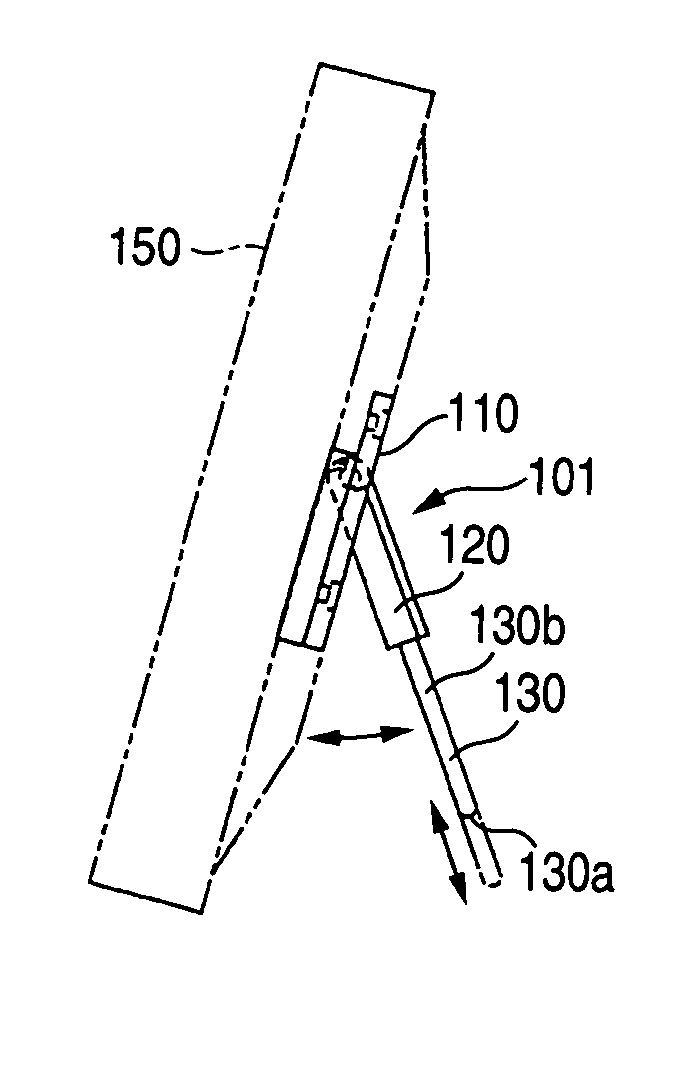
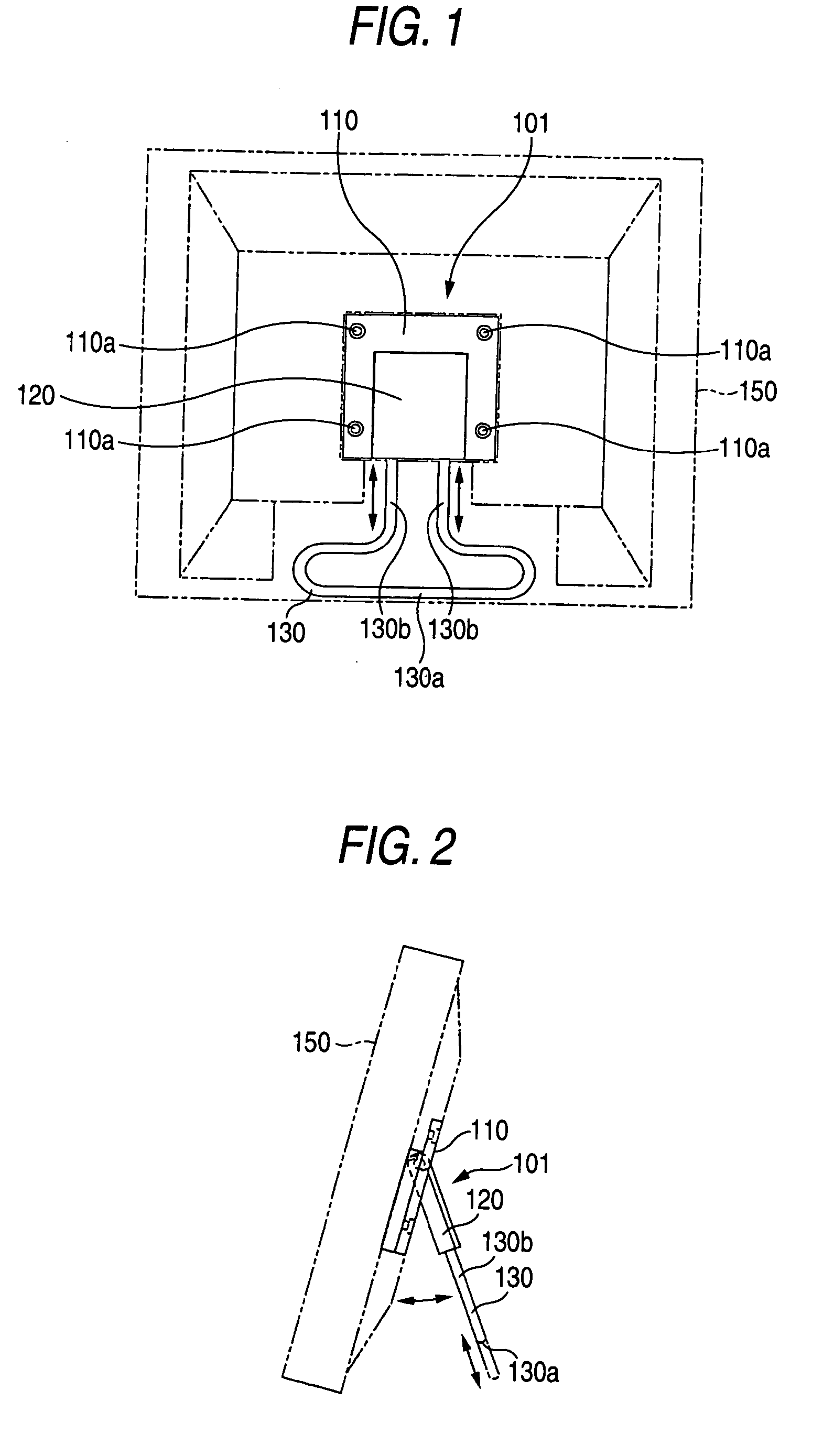
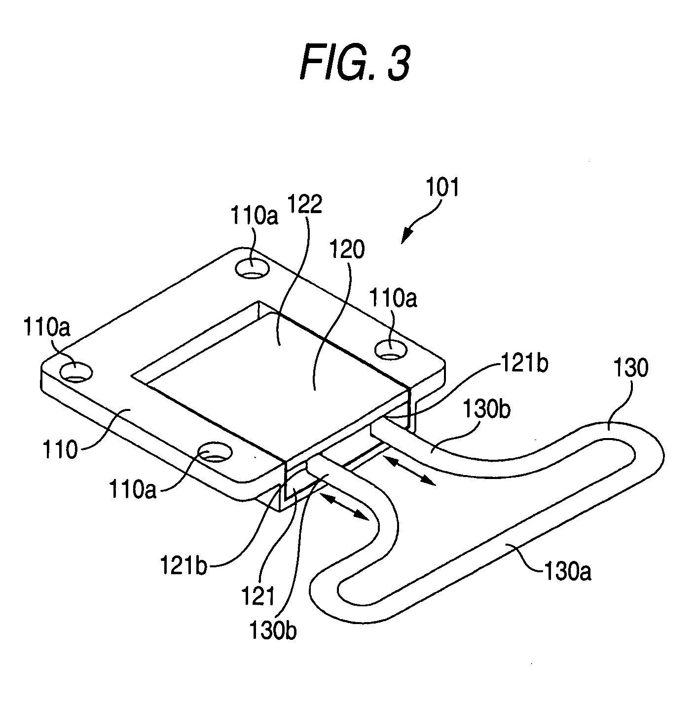
[0065]FIG. 1 is a rear view showing a liquid crystal television provided with a stand for liquid crystal televisions, according to an embodiment of the invention. FIG. 2 is a side view showing the liquid crystal television shown in FIG. 1 when viewed from the left side. FIG. 3 is a perspective view showing the stand for liquid crystal televisions, according to the embodiment of the invention FIG. 4 is an exploded, perspective view showing the stand for liquid crystal televisions, according to the embodiment of the invention and shown in FIG. 3. FIG. 5 is a partial, enlarged view showing an internal construction of the stand for liquid crystal televisions, according to the embodiment of the invention and shown in FIG. 3. FIG. 6 is a fragmentary, cross sectional view, taken along the line 200-200, of the stand for liquid crystal televisions, according to the embodiment of the invention and shown in F...


PUM

PropertyMeasurementUnit
angleaaaaaaaaaa
forceaaaaaaaaaa
pushing forceaaaaaaaaaa

Abstract

In a stand of liquid crystal display, a holding member may include a slider, a lower cover, a leaf spring that abuts against a side of the slider, a push-force adjusting member. The push-force adjusting member includes a push member, which has a tapered portion and pushes the leaf spring, and a screw member, which adjusts a height of the tapered portion of the push member relative to the leaf spring. The push-force adjusting member serves to adjust a push force of the leaf spring on the side of the slider. The lower cover has an adjustment hole, through which the screw member can be adjusted from outside. The slider may have a rectangular-shaped. The lower cover may have a first stopper, against which an upper end surface of the slider abuts, and a second stopper, against which a lower end surface of the slider abuts.

Description

BACKGROUND OF THE INVENTION [0001] 1. Field of the Invention [0002] The present invention relates to a stand for liquid crystal display including a television, and more relates to a stand for the liquid crystal display provided with a stand member that supports the liquid crystal display in an inclined state at a predetermined angle. [0003] 2. Description of the Related Art [0004] Conventionally, a stand that supports an article such as liquid crystal televisions is known (for example, see JP-UM-A-4-36382 and Japanese Utility Model Registration NO. 3065530). [0005] JP-UM-A-4-36382 discloses a construction, in which an elevation angle adjusting stand is pivotally mounted on a back surface of a liquid crystal display. Also, Japanese Utility Model Registration No. 3065530 discloses a stand that stands an article and includes a gear portion turnably mounted on a body, a slide gear that meshes with the gear portion and is mounted slidably on the body, and a leg that supports the body on ...

Claims


Application Information

Patent Timeline
Patent Type & Authority Applications(United States)
IPC IPC(8): F16M11/10
CPCF16M2200/041F16M11/10
Inventor OGAWA, MASUO
Owner FUNAI ELECTRIC CO LTD
Why Eureka
Try Eureka