Error recognition for power ring

a power ring and error recognition technology, applied in the direction of dynamo-electric machines, dc source parallel operation, ac network voltage adjustment, etc., can solve the problems of failure of the internal electrical current supply of all connected devices, failure of all electrical consumers connected to the power ring, etc., to achieve stable transmission of electrical power.

Inactive Publication Date: 2005-01-06
RHEINMETALL LANDSYST
View PDF12 Cites 26 Cited by
  • Summary
  • Abstract
  • Description
  • Claims
  • Application Information

AI Technical Summary

Benefits of technology

[0009] One advantage of the present invention lies in that the previously experienced disadvantage of the prior art power ring, in which there is a long time period delay while the failed conductor segment is identified and isolated which requires successive powering up of the power ring after an electrical failure, can be avoided. In addition, the power ring device in accordance with the present invention is able to measure the electrical power consumption of the individual connected electrical energy consumers that are connected to the power ring.
[0010] Thus, in accordance with the present objectives, the present invention provides a first apparatus embodiment, specifically, a power ring device in a military vehicle for supplying electrical power to electrical consuming devices of the vehicle. The power ring device includes: (a) a ring conductor; (b) a plurality of controllers operating as control and switching devices, wherein each controller is connected to the ring conductor and each controller includes a first control unit; (c) a plurality of paired pick ups disposed on the ring conductor, wherein each pair of pick ups connects either an electrical consumer device or an electrical power supply to the ring conductor and to one of the plurality of controllers, wherein a first pair of pick ups of a first controller is connected to a first power supply; and (d) a plurality of current sensor signal lines connecting each control unit of the plurality of controllers so as to form a data connection between the controllers that supervise and control transmission of electrical power along the ring conductor. Each controller further comprises: i. a right side and a left side, and each controller includes a right sided switch element and a left sided switch element connected to the control unit and the ring conductor; and ii. a right sided current sensor and a left sided current sensor connected to the ring conductor, to the first control unit, and to the plurality of current sensor signal lines so that a first current value measured by the left sided current sensor of the first controller is transmitted as data to the first control unit of a second controller.
[0011] In accordance with a second apparatus embodiment of the present invention, the plurality of controllers operate together to provide an intelligent control unit for controlling the transmission of electrical power from the first power supply to a first current consumer connected by a second pair of pick ups of a second controller to the ring conductor, wherein the intelligent control unit operates to maintain stable transmission of electrical power to the first current consumer by isolating a short circuit or a power surge in the ring conductor.
[0012] In accordance with a third apparatus embodiment of the present invention, the control units of the plurality of controllers operate together as control nodes to provide an intelligent control unit for controlling the transmission of electrical power from the first power supply to a first current consumer connected by a second pair of pick ups of a second controller to the ring conductor, wherein the intelligent control unit operates to maintain stable transmission of electrical power to the first current consumer by isolating an electrical disturbance in the ring conductor, wherein the electrical disturbance is either a short circuit or a power surge.
[0013] In accordance with a fourth apparatus embodiment of the present invention, each first control unit provides a control node for an integrated intelligent control unit, and each first control unit comprises a device for voltage measurement and a device for conduction protection with status indication.
[0014] In accordance with a fifth apparatus embodiment of the present invention, the integrated intelligent control unit includes a master controller connected to send control signals to each first control unit.

Problems solved by technology

A short circuit in the ring conductor of the conventional power ring has the disadvantage that all electrical consumers connected to the power ring are no longer supplied with electrical power.
Military vehicles, however, have special requirements and it is an undesirable shortcoming that the internal electrical current supply for all connected devices should fail due to a simple short circuit.
Furthermore, repair shops are not always readily available in places where military vehicles may travel.
However, this technique of isolating the failed conductor segment, by systematically testing each segment while the ring conductor is unable to conduct electricity has disadvantages.
In particular, it is a disadvantage that the power ring, in a case of electrical failure (i.e., short circuit), must be subsequently shut off completely, thereby interrupting the energy supply to all of the connected electrically consuming devices.
In addition, the power ring device disclosed by Joehnke et al. cannot readily locate failures that are sporadic failures.

Method used


Image

  • Error recognition for power ring
  • Error recognition for power ring
  • Error recognition for power ring

Examples


Embodiment Construction

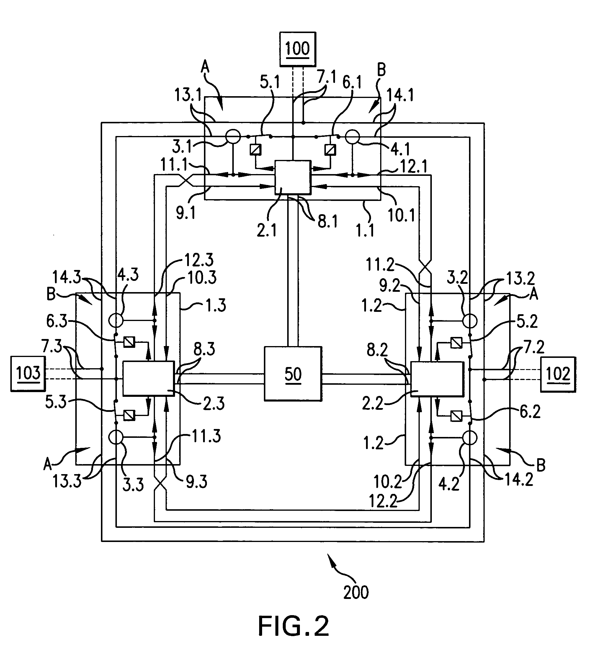
[0049] The power ring apparatus of the present invention is described in FIGS. 1 through 4, where like reference characters have been used to label like parts. FIG. 5 illustrates a vehicle 400 that has a power ring device in accordance with the present invention incorporated therein.

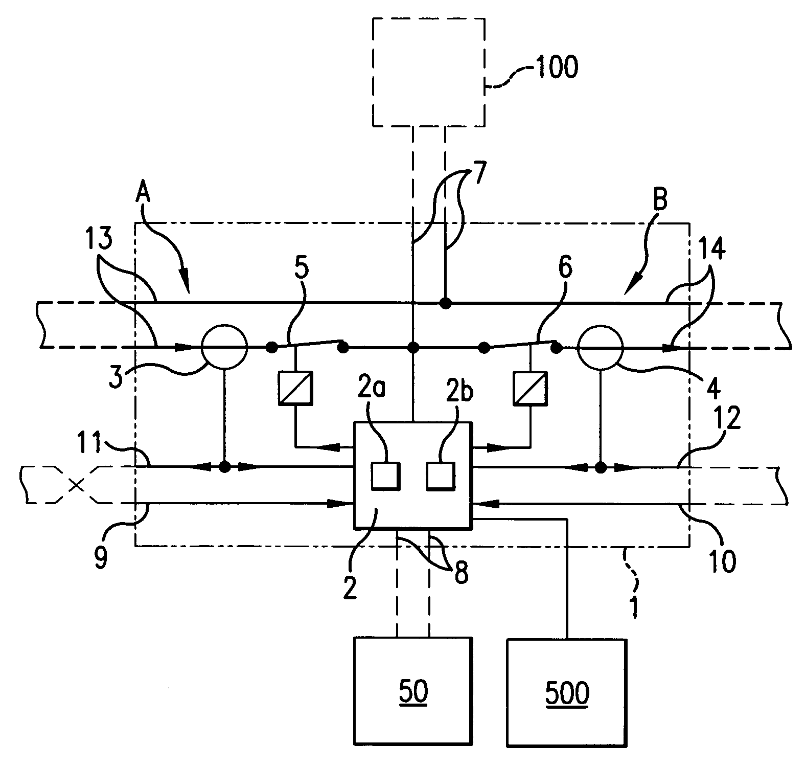
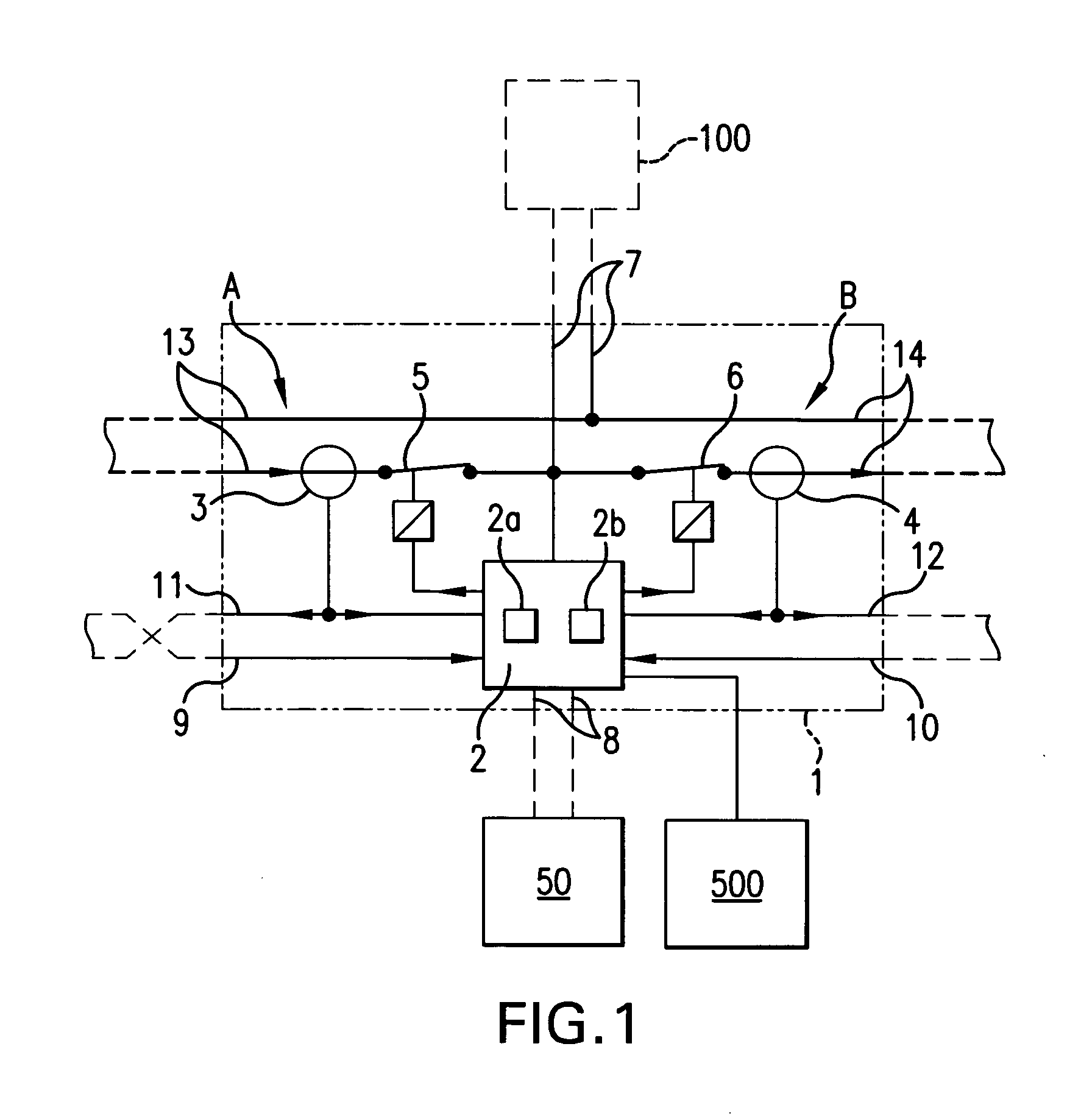
[0050]FIG. 1 schematically shows a pick up controller in accordance with the present invention, which includes a pick up controller 1 with a housing that houses the following components: a control unit 2; current sensors 3 and 4; and switch elements 5 and 6, which are connected with various electrical conductors 9 to 14 (also referred to as “lines” or “wires”) as illustrated. The paired pick ups 7, of either a power supply or an electrical consumer, are connected to conductor lines 13 and 14. Conductor lines 13 and 14 together form a conductor ring 13, 14. Signal lines 8, for conducting failure signals to a failure indicator 50, are connected to the control unit 2. Current sensor signal lines 9 and 10 a...


PUM


Abstract

A power ring device that includes: a ring conductor; a plurality of controllers, each controller being connected to the ring conductor and includes a first control unit; a plurality of paired pick ups, wherein each pair connects either an electrical consumer device or an electrical power supply to the ring conductor and to one of the plurality of controllers, wherein a first pair of pick ups of a first controller is connected to a first power supply; and a plurality of current sensor signal lines connecting each control unit to form a data connection; wherein each controller has a right and left side, a right sided and left sided switch elements; and a right sided and left sided current sensors connected so that a first current value measured by the left sided current sensor of the first controller is transmitted as data to the first control unit of a second controller.

Description

FIELD OF THE INVENTION [0001] The invention relates to an improvement in a power ring device, such as would be used in a military vehicle or non-military vehicle, for supplying electrical power to various electrical consuming devices incorporated within the vehicle. Specifically, the power ring device constructed in accordance with the present invention includes an errors recognition feature with a mechanism for compensating for any electrical error occurring in the power ring device. BACKGROUND OF THE INVENTION [0002] It is known that to supply devices with electrical energy, as individual components and consumers of electrical power in a vehicle such as a military vehicle, a so-called “power ring” is frequently employed. A power ring is a ring conductor that transports output energy and that connects each electrically consuming device with a power generator, which is different from star-shaped electrical connections that can be employed to connect each electricity consuming device...

Claims


Application Information

Patent Timeline
Patent Type & Authority Applications(United States)
IPC IPC(8): B60R16/02B60R16/03H02H7/28H02J1/00
CPCB60R16/03H02J1/00H02H7/28H02J2310/46
Inventor SAUER, BODOREHDER, RALF
Owner RHEINMETALL LANDSYST
Why Eureka
Try Eureka