Method of manufacturing micro lens, micro lens, optical device, optical transmission device, head for laser printer, and laser printer

Inactive Publication Date: 2005-01-06
SEIKO EPSON CORP
View PDF13 Cites 8 Cited by
  • Summary
  • Abstract
  • Description
  • Claims
  • Application Information

AI Technical Summary

Benefits of technology

[0033] According to the laser printer, since it includes the head for the laser printer having the excellent drawi

Problems solved by technology

However, in the molding method using the mold or the photolithography method, since the mold or a complicated manufacturing process is needed in order to form the micro lens, problems arise in that the cost thereof becomes high and it is difficult to form

Method used


Image

  • Method of manufacturing micro lens, micro lens, optical device, optical transmission device, head for laser printer, and laser printer
  • Method of manufacturing micro lens, micro lens, optical device, optical transmission device, head for laser printer, and laser printer
  • Method of manufacturing micro lens, micro lens, optical device, optical transmission device, head for laser printer, and laser printer

Examples


Embodiment Construction

[0041] Exemplary embodiments of the present invention are explained in detail below.

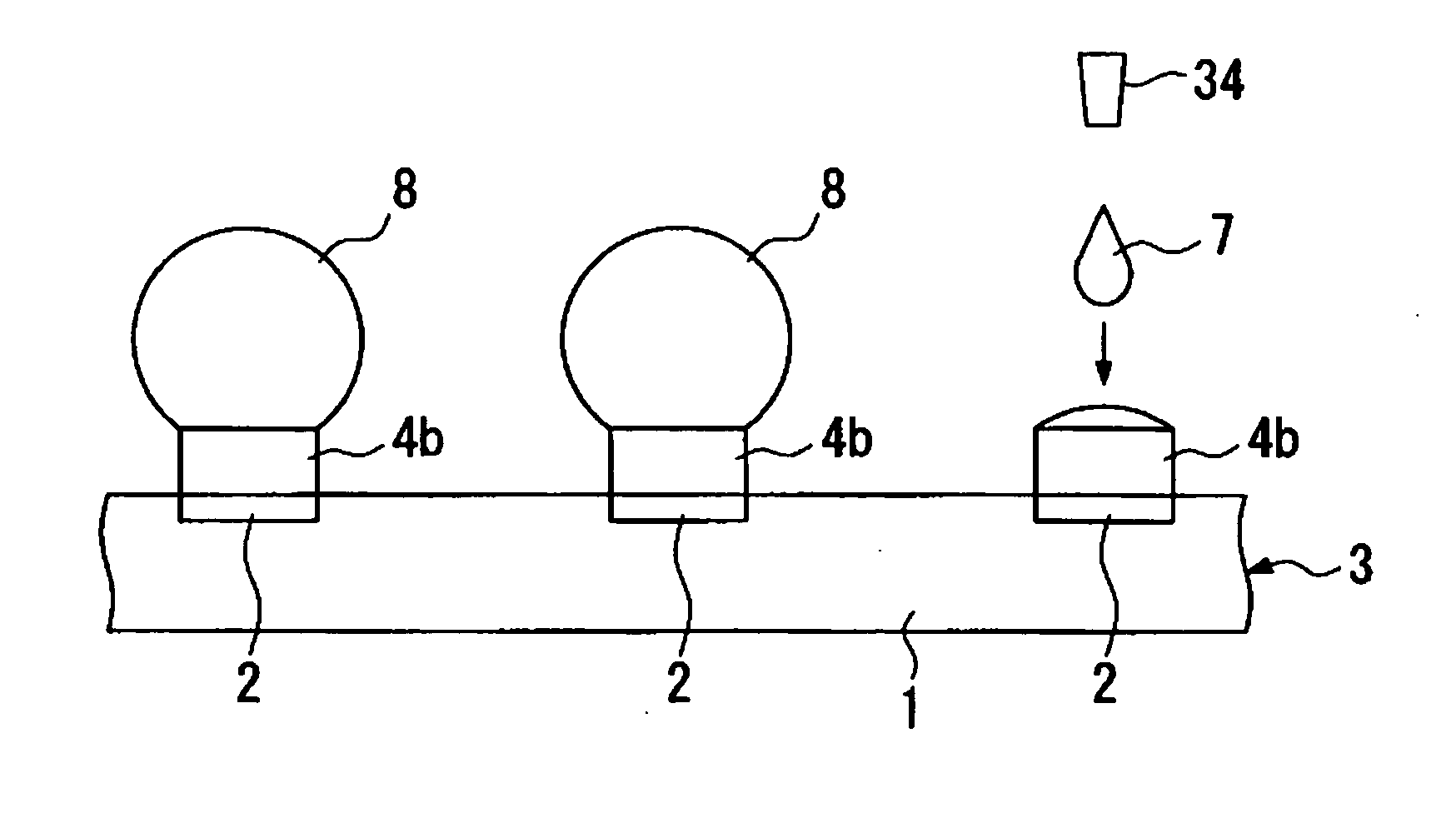
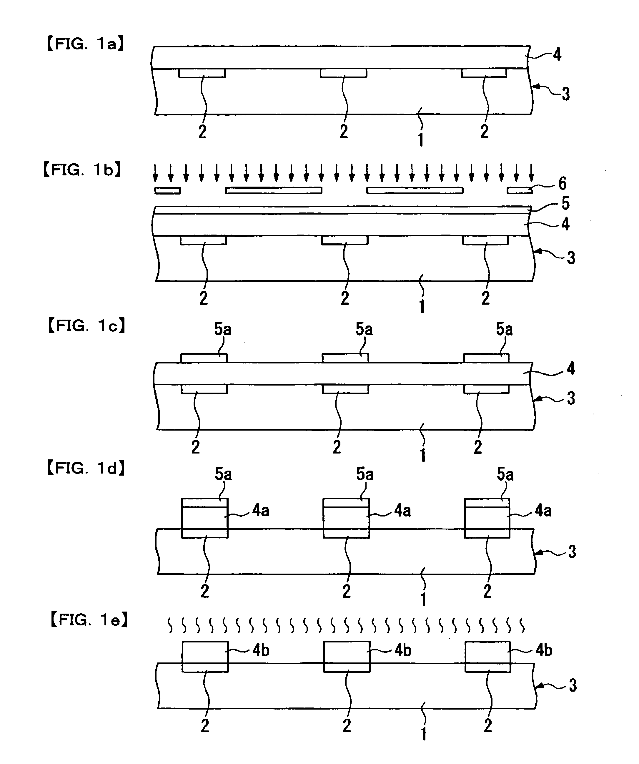
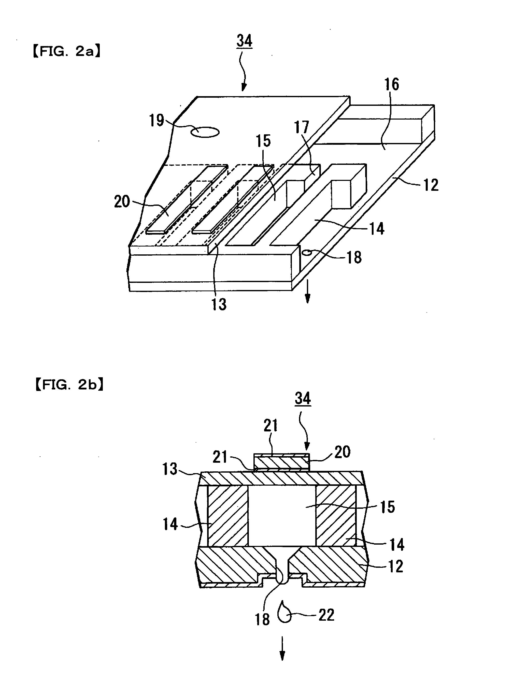
[0042] First, a method of manufacturing a micro lens according to the present invention is explained. The method of manufacturing the micro lens according to the present invention includes: forming a foundation member on a base, subjecting the upper surface of the foundation member to lyophobic processing; and ejecting lens material on the lyophobic-processed foundation member in a plurality of dots by a droplet ejecting method to form the micro lens on the foundation member.

[0043] Here, in the present invention, “base” means a substance having a surface on which the foundation member can be formed, and, in particular, refers to a glass substrate or a semiconductor substrate, or a material having various functional thin films or functional elements formed thereon. In addition, the surface on which the foundation member can be formed may be a curved surface or a flat surface; that is, the shape of t...


PUM


Abstract

The invention provides a method of manufacturing a micro lens, a micro lens, an optical device having the micro lens, an optical transmission device, a head for a laser printer, and a laser printer, by which excellent lens characteristics, such as a condensing function, can be obtained by optionally controlling the shape thereof. The micro lens is formed on the upper surface of a foundation member formed on a base. The upper surface of the foundation member is subjected to lyophobic processing. The micro lens is formed by ejecting lens material in a plurality of dots by a droplet ejecting method.

Description

BACKGROUND OF THE INVENTION [0001] 1. Field of Invention [0002] The present invention relates to a method of manufacturing a micro lens, a micro lens obtained by the method, an optical device having the micro lens, an optical transmission device, a head for a laser printer, and a laser printer. [0003] 2. Description of Related Art [0004] Related art optical devices have a plurality of minute lenses, referred to as micro lenses. These optical devices include, for example, light-emitting devices having lasers, optical interconnections formed of optical fibers, and charge coupled devices having a condensing lens to collect incident light. [0005] The micro lenses constituting such optical devices can be manufactured by a molding method using a mold or a photolithography method (for example, as disclosed in Japanese Unexamined Patent Application Publication No. 2000-35504). [0006] The related art also includes a method of forming micro lenses having a minute pattern using the droplet eje...

Claims


Application Information

Patent Timeline
IPC IPC(8): B05D1/26B29D11/00G02B3/00
CPCB29D11/00365G02B3/005G02B3/0012G07B3/04G07D2211/00
Inventor HASEI, HIRONORI
Owner SEIKO EPSON CORP
Why Eureka
Try Eureka