Coagulating electrosurgical instrument with tissue dam

a tissue dam and electrosurgical technology, applied in the field of electrosurgical instruments, can solve the problems of tissue shrinkage, thermal damage to adjacent structures, blood vessel thrombosis, etc., and achieve the effect of increasing hemostasis and decreasing thermal damage to lateral tissues

Inactive Publication Date: 2005-01-06
WITT DAVID A +3
View PDF7 Cites 318 Cited by
  • Summary
  • Abstract
  • Description
  • Claims
  • Application Information

AI Technical Summary

Benefits of technology

[0023] In a further embodiment a tissue dam is included on at least one jaw to help contain tissue within the desired coagulation area, and thereby help contain current density between the electrodes, thereby decreasing lateral tissue thermal damage and increasing hemostasis.

Problems solved by technology

This creates a small envelope of steam around the electrodes of the electrosurgical instrument, and the steam vaporizes the tissue to cause cellular dehydration, denaturation of proteins, and tissue shrinkage, leading to blood vessel thrombosis.
Thermal damage to adjacent structures can occur due to this spread of thermal energy outside the jaws of the instrument.
Because of the spread of thermal energy outside the jaws of the instrument, it is difficult to coagulate long sections of tissue, such as bowel, lung, or larger blood vessels, without significant lateral thermal spread.
Over- coagulation frequently occurs, resulting in tissue sticking to the jaws of the instrument.
When the jaws of the instrument are opened, if the tissue sticking is severe, the tissue can be pulled apart, thus adversely affecting hemostasis.
Under-coagulation can occur if insufficient energy has been applied to the tissue, and the resulting hemostasis will be incomplete.

Method used


Image

  • Coagulating electrosurgical instrument with tissue dam
  • Coagulating electrosurgical instrument with tissue dam
  • Coagulating electrosurgical instrument with tissue dam

Examples


Embodiment Construction

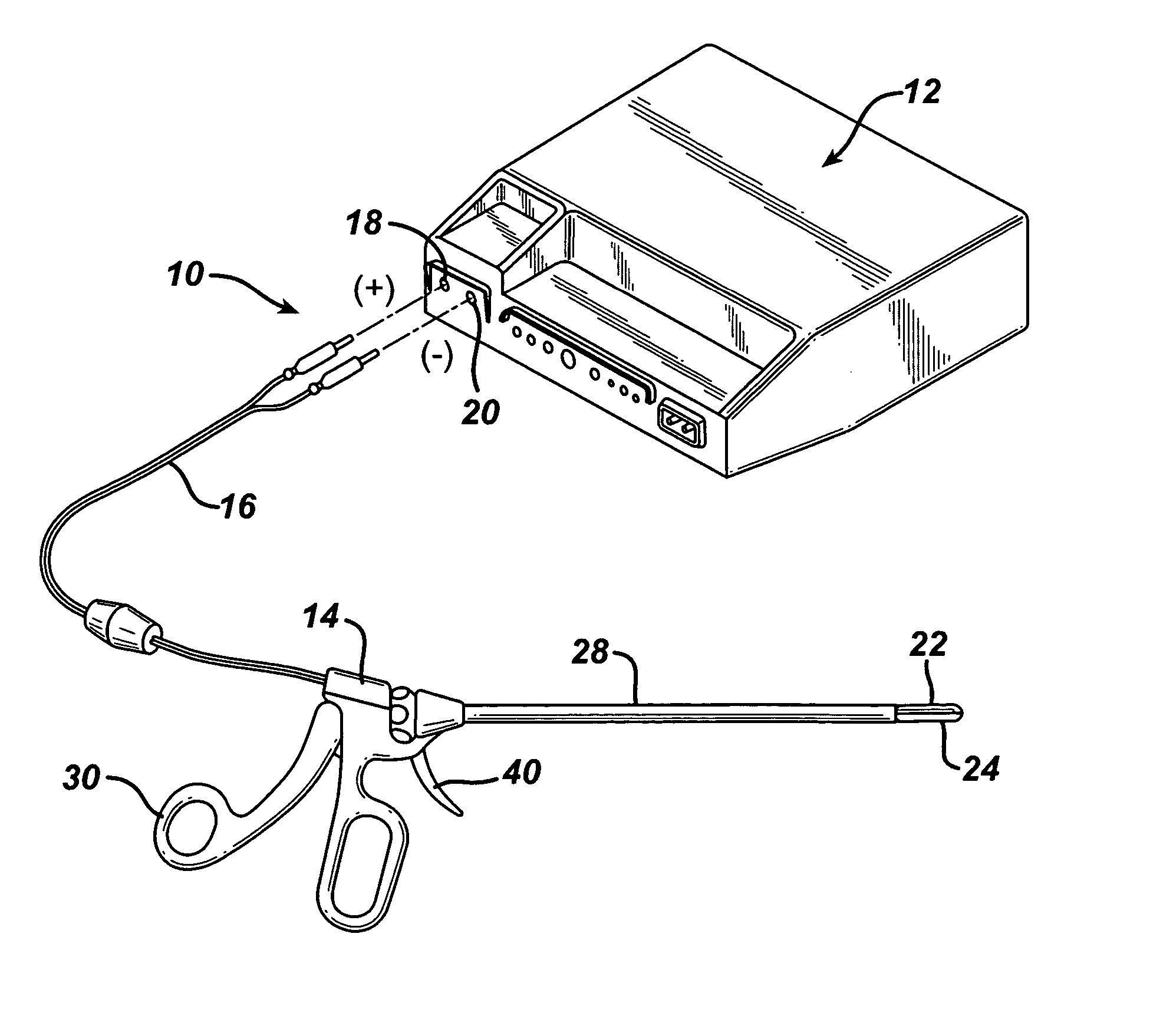
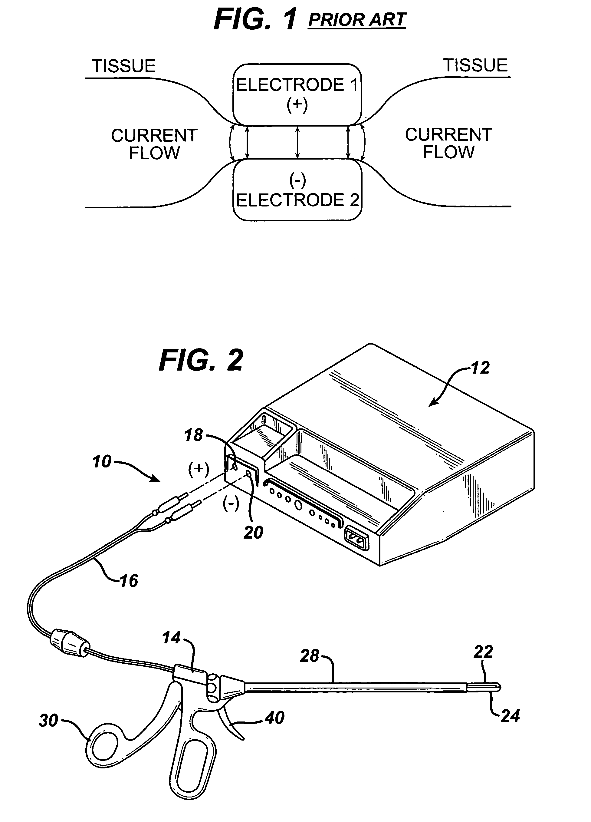
[0075] Turning to FIG. 2, there is seen a perspective view of an electrosurgical instrument system, generally designated 10, embodying the present invention. The illustrated system includes an RF energy generator 12, a hand-held, endoscopic electrosurgical graspers 14, and a cable 16 that connects the graspers 14 to the plug clip receptacles 18, 20 for positive and negative bipolar outputs of the generator 12. While the illustrated graspers 14 are endoscopic graspers for use in minimally invasive surgical procedures, the invention of the present application is equally applicable to graspers designed for use in open surgical procedures.

[0076] The illustrated RF generator 12 may be, for example, a unitary monopolar-bipolar RF generator, such as the PEGASYS (Trademark of Ethicon Endo-Surgery Inc., Cincinnati Ohio) generator, and thus also include plug clip receptacles for the mono-polar active and return terminals. However, for the purposes of the present invention, only the bipolar c...


PUM


Abstract

A bipolar electrosurgical instrument having a pair of relatively moveable jaws, each of which includes a tissue contacting surface. The tissue contacting surfaces of the jaws are in face-to-face relation with one another, and adjacent each of the tissue contacting surfaces are first and second spaced-apart electrodes that are adapted for connection to the opposite terminals of a bipolar RF generator so as to generator a current flow between the electrodes. The first and second electrodes of one jaw are in offset opposed relation, respectively, with the first and second electrodes of the other jaw. A cutting portion is provided between the jaws. The cutting portion is moveable to provide the instrument with a scissors-like capability or a grasper-like capability, depending on the position of the cutting portion. A tissue dam is included on at least one jaw to help contain tissue within the desired coagulation area, and thereby help contain current density between the electrodes, thereby decreasing lateral tissue thermal damage and increasing hemostasis.

Description

CROSS REFERENCE TO RELATED APPICATIONS [0001] This application is related to, and claims the benefit of provisional patent application Serial No. 60 / 266,055 filed Feb. 2, 2001; and provisional patent application Serial No. 60 / 264,644 filed Jan. 26, 2001, which are hereby incorporated herein by reference.FIELD OF THE INVENTION [0002] The present invention relates, in general, to electrosurgical instruments and, more particularly, to an electrosurgical combination grasper with a tissue dam for surgical applications. BACKGROUND OF THE INVENTION [0003] The application of heat to treat bleeding wounds dates back to antiquity, with a hot iron being widely applied in medieval times to cauterize battle wounds to stop bleeding. In cauterization, the essential mechanism behind the treatment is using conductive heat transfer from a hot object to raise the temperature of the bleeding tissue sufficiently high to denature the tissue proteins, or heat the blood sufficiently high to cause a thrombu...

Claims


Application Information

Patent Timeline
Patent Type & Authority Applications(United States)
IPC IPC(8): A61B18/14A61B18/12
CPCA61B17/32A61B18/1442A61B2017/2945A61B2018/00589A61B2018/00601A61B2018/0063A61B2018/1457A61B2018/142A61B2018/1432A61B2018/146A61B18/20A61B2018/1455A61B2018/00875
Inventor WITT, DAVID A.FALLER, CRAIGBAXTER, CHESTER O. IIICUMMINGS, JOHN F.
Owner WITT DAVID A
Why Eureka
Try Eureka