Method and apparatus for injection molding light metal alloy

a technology of light metal alloy and injection molding, which is applied in the direction of metal founding, chemical apparatus and processes, etc., can solve the problems of large size of the apparatus, excessive height of the entire apparatus, and defective products, so as to improve the quality of the products, improve the resistance to passage, and ensure the effect of molding operation

Inactive Publication Date: 2005-01-13
KOBE STEEL LTD
View PDF11 Cites 24 Cited by
  • Summary
  • Abstract
  • Description
  • Claims
  • Application Information

AI Technical Summary

Benefits of technology

[0013] An object of the present invention is to provide a method of and an apparatus for injection molding, capable of injection molding light metal molding products at high quality with less pores or shrinkage, without excessively enlarging the size of the height for the injection molding machine.

Problems solved by technology

Since the starting materials are solid metals, any of the methods described above involves a problem that abrasion or flexion occurs violently in the upstream of the extrusion screw and a load torque has to be increased or a heating and stirring channel has to be enlarged in the screw extruder thereby making the size of the apparatus larger.
Further pores are liable to be mixed in molding products due to involvement of an inert gas to result in defective products.
However, since the discharge port at the lower end of the vertical chamber is directly connected detachably to an upper portion of a molding die disposed therebelow, this method involves a drawback that the height of the entire apparatus is excessively large to increase the machine cost and also increases the maintenance cost.
Further, in the injection molding system described above, since the slurry is injected by rapidly lowering the extrusion screw in the material in which the liquid phase and the semi-solidification phase are mixed together, this involves an inherent problem that a screw flight is abraded violently and the slurry deposited in the upper portion of the screw tends to damage the shaft seal portion.
However, in the system with a separated injection plunger described above, since a large melting furnace (feeder 20 with heater 25 shown in FIG. 1 of Japanese Laid-Open Hei 9-103859) is connected directly to an upper portion of the chamber, there is a limit for making the compact machine.
Further, since a melting furnace for heating the solid material into a molten metal is directly connected to the upper portion of the chamber in this system, it is not favorable in view of the thermal stability of the molten metal and the safety.
Further, when the melting furnace is connected to the upper portion of the chamber, it results in an inherent problem that the flow rate control is difficult

Method used


Image

  • Method and apparatus for injection molding light metal alloy
  • Method and apparatus for injection molding light metal alloy
  • Method and apparatus for injection molding light metal alloy

Examples


first embodiment

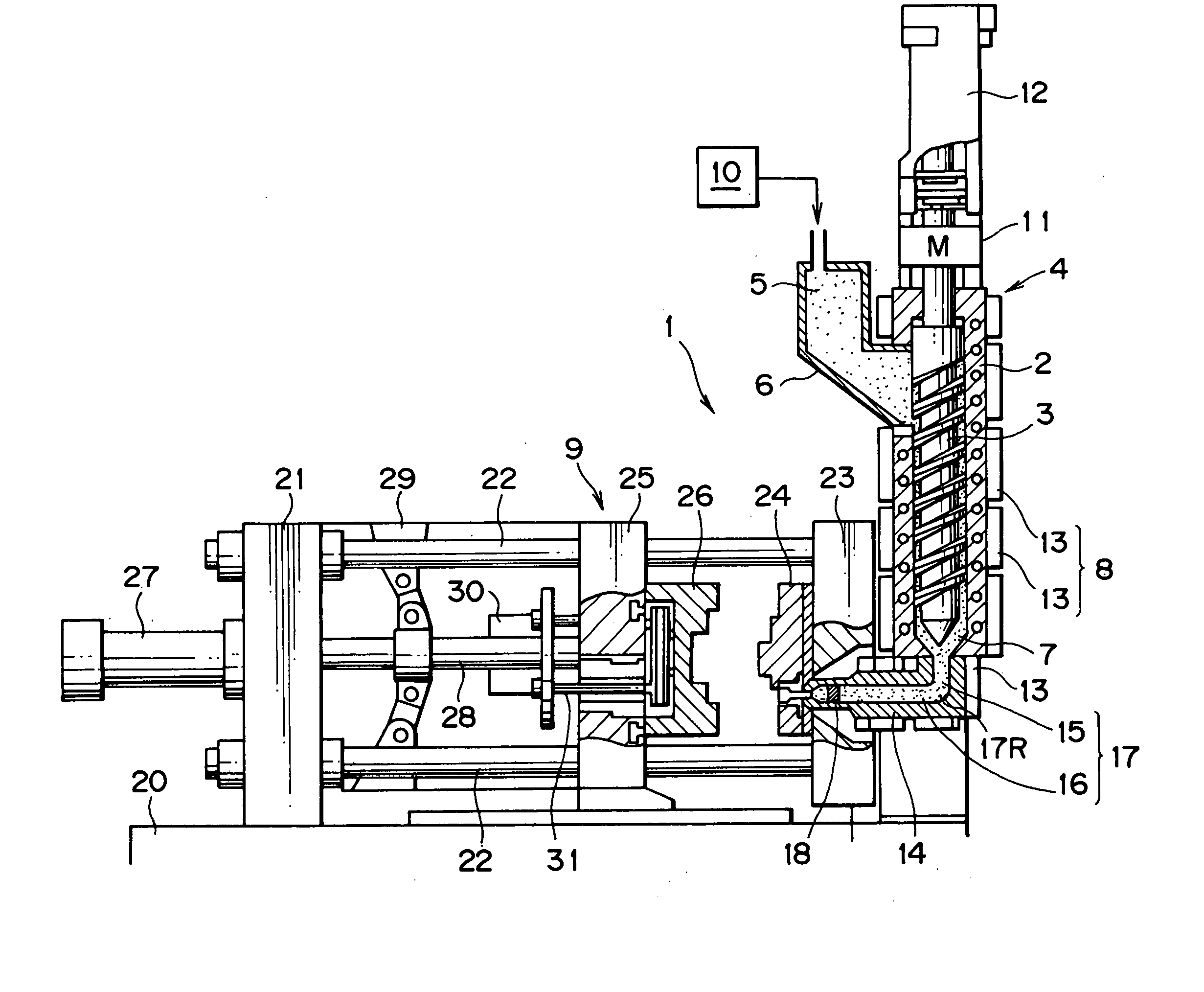
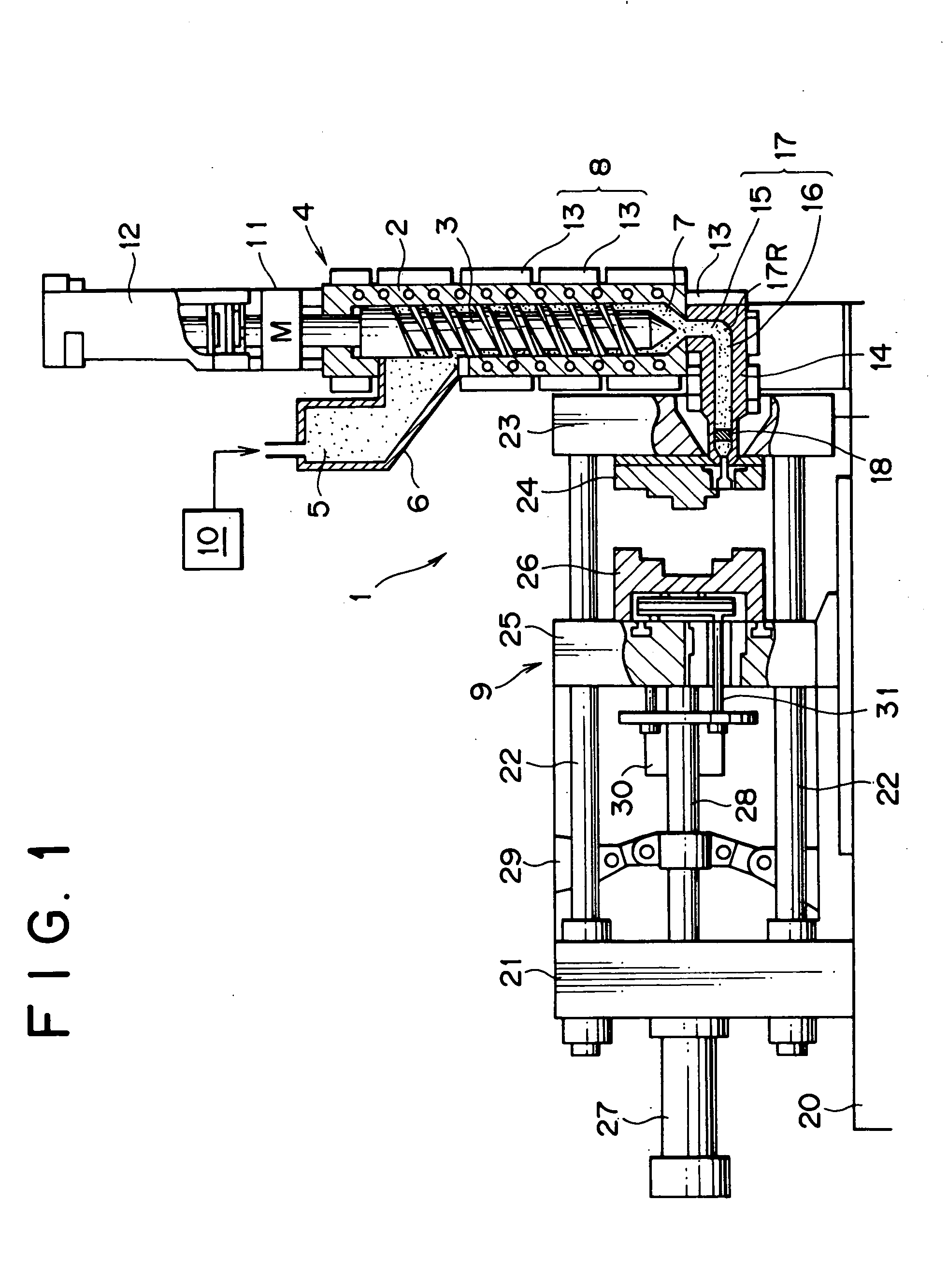
[0063]FIG. 1 shows the present invention.

[0064] An injection molding apparatus 1 for light metal alloys according to this embodiment comprises a screw extruder 4 disposed vertically and having an extrusion screw 3 disposed rotatably at the inside of a chamber 2 and a hopper 6 connected to the upper end of the chamber 2 for storing molten metal 5.

[0065] Further, the apparatus 1 comprises a temperature control unit 8 used for temperature control, for example, cooling such that the molten metal 5 supplied from the hopper 6 into the chamber 2 is formed into semi-solidified slurry 7 and a clamping device 9 into which the semi-solidified slurry 7 discharged from a discharge port at a lower end of the chamber 2 is injected.

[0066] Among the constituent components of the apparatus 1, the hopper 6 is adapted to receive the molten metal 5 melted in a melting furnace 10 and store the same in a molten state, and a lower end opening of the hopper 6 is connected to an upper end of the chamber 2....

second embodiment

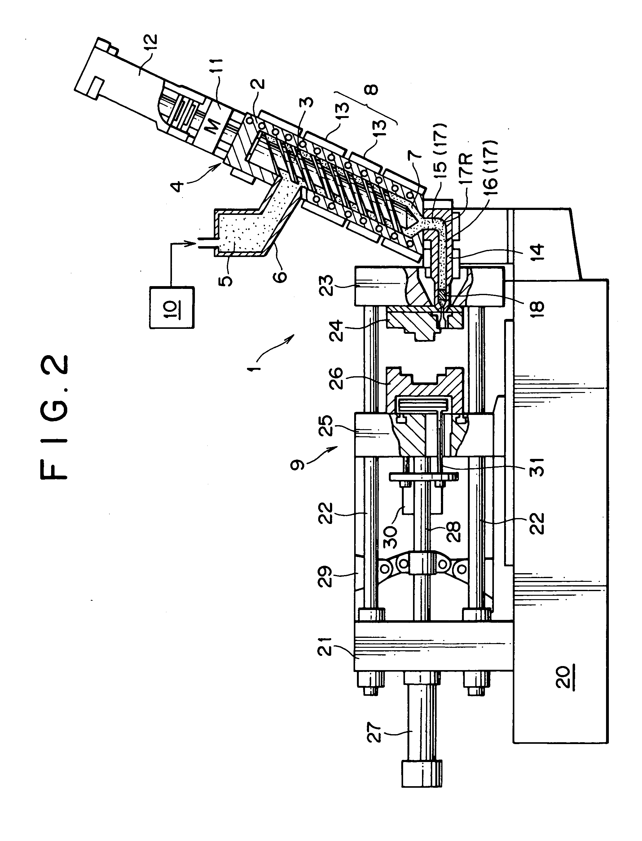
[0102]FIG. 2 shows the present invention.

[0103] In this embodiment, a chamber 2 for a screw extruder 4 is inclined in a state somewhat turned down to the side opposite to the clamping device 9, by which the height for the entire apparatus can be suppressed further lower compared with the case of the first embodiment.

[0104] The degree of inclination of the screw extruder 4 is set substantially equal with the helical angle of the extrusion screw 3 and, at such degree of inclination satisfactory stable operation can be conducted without removing the pores at the inside of the chamber 2 or without deposition of the semi-solidified slurry 7 to the upper portion of the shaft.

[0105] In the present invention, “substantially vertical” means not only that the chamber 2 is disposed vertically but also that it is inclined to such an extent as removal of bubbles can be saved at the inside of the chamber 2 or deposition does not occur to the upper portion of the shaft.

[0106] Since other consti...

third embodiment

[0107]FIG. 3 shows the present invention.

[0108] In this embodiment, an extrusion screw 3 is inserted in a chamber 2 so as not to move in the axial, namely, vertical direction, so that the injection cylinder 12 is not disposed to the upper end of a driving motor 11.

[0109] Instead, a discharge port at the lower end of a chamber 2 is connected with an upper portion at the front end of a metering cylinder (connection member) 34, in which an injection plunger 33 protruding and retracting horizontally is inserted therein. An injection flow channel 17 comprising a vertical first channel 15 and a horizontal second channel 16 is constituted at the front end of the metering cylinder 34, and a check valve (not illustrated) for preventing the semi-solidified slurry 7 in the second channel 16 from flowing backwardly to the chamber 2 is disposed in the first channel 16.

[0110] Further, an injection cylinder 36 is disposed to the rear end of the metering cylinder 34 for protruding an injection pl...


PUM

PropertyMeasurementUnit
temperatureaaaaaaaaaa
circumferenceaaaaaaaaaa
compression ratioaaaaaaaaaa

Abstract

The apparatus of the invention is an injection molding apparatus of a type adapted to cool a molten metal under shearing by an extrusion screw in a substantially vertical chamber into a semi-solidified slurry and then inject the semi-solidified slurry discharged from a discharge port at the lower end of a channel into molding plates, in which a clamping device is adapted to open or close a movable plate relative to a stationary plate in the horizontal direction, and a connection member having, at the inside, a vertical first channel and a second channel extending in the horizontal direction from the lower end of the first channel and in communication with the stationary plate is connected to the discharge port at the lower end of the chamber. Since this can inject and mold light metal molding products of high quality with less pore or shrinkage without excessively enlarging the size for the height of the apparatus, casting products of high quality can be obtained at a reduced cost by injection molding.

Description

BACKGROUND OF THE INVENTION [0001] 1. Field of the Invention [0002] The present invention concerns a method of and an apparatus for injection a molding light metal alloy such as of magnesium and aluminum. [0003] 2. Description of the Related Art [0004] As a method of molding light metal alloy materials in a manner similar with injection molding of resins, there has been known a method of injecting a light metal alloy material in a semi-solidified slurry into a molding die. Generally, raw metal alloy materials are formed into a semi-solidified state by heating a raw material pellet in a screw extruder as disclosed in International Patent Publication Hei 3-504830 or by granulating raw ingot materials heated into a semi-molten state and then heating the same in a screw extruder as disclosed in Japanese Patent No. 2832625 or Japanese Laid-Open Hei 9-108805. [0005] Since the starting materials are solid metals, any of the methods described above involves a problem that abrasion or flexio...

Claims


Application Information

Patent Timeline
Patent Type & Authority Applications(United States)
IPC IPC(8): B22D17/00B22D17/20B22D17/30B22D21/00
CPCB22D17/007B22D17/2015Y10S164/90B22D21/002B22D17/30B22D17/2023B22D17/2281
Inventor TANAKA, TATSUYASOEJIMA, MUNENORITAKAHASHI, KATSUNORIKANDA, TAKESHIFUJISAWA, KAZUHISA
Owner KOBE STEEL LTD
Why Eureka
Try Eureka