
Redundant power distribution system

Inactive Publication Date: 2005-01-13
THE BOEING CO
View PDF12 Cites 63 Cited by
  • Summary
  • Abstract
  • Description
  • Claims
  • Application Information

AI Technical Summary

Benefits of technology

[0019] Another advantage of the present invention is that it provides a redundant regulator circuit that exhibits a low drop in voltage across the regulator, that has an adjustable output voltage, that does not have any reverse current flow therethrough, that has over current protection, thermal protection, and that is capable of withstanding reverse voltage on input.
[0020] Furthermore, the present invention is flexible and versatile in that it provides multiple power distribution configurations that may be easily modified for various power distribution applications.

Problems solved by technology

Malfunctioning of any of the components can result in a large-scale system malfunction, potential damage to a system, or potential injury to a system operator or occupant.
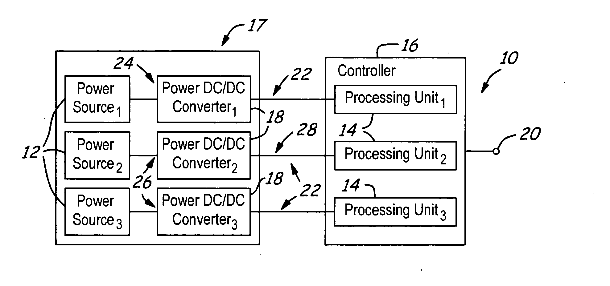
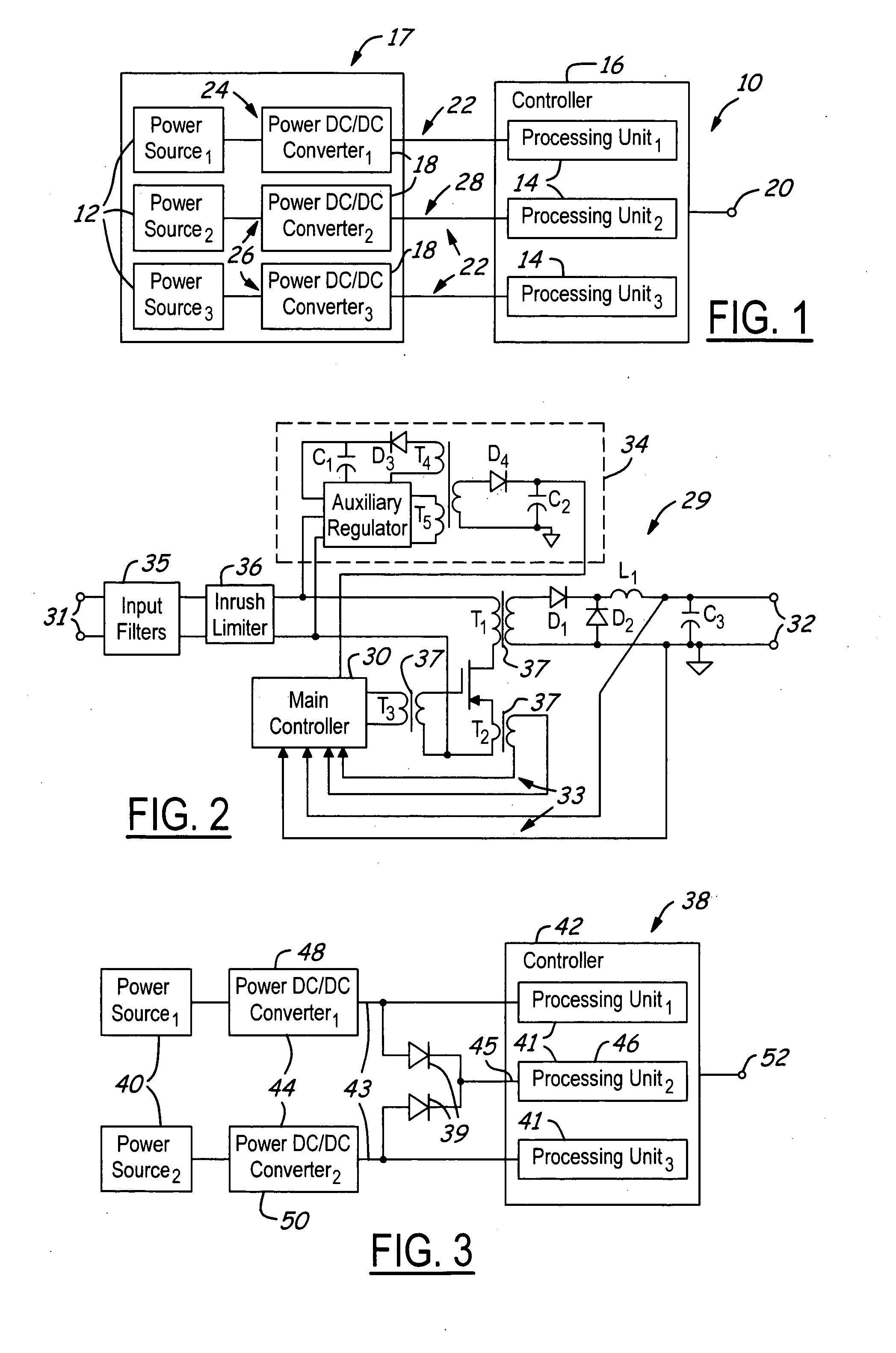
Unfortunately, when a second line is also malfunctioning, such as line 28, a majority determination cannot be easily performed, since one may not be able to determine which of the remaining two lines 26 is correct and which is malfunctioning.
When a power distribution system does not have isolated power sources, ground current may flow through other undesirable return paths and jeopardize system operations and it also introduces an unsafe environment for system operators.
Thus, without redundancy a “single-point of failure” may occur, causing a critical electronic system to malfunction from, just a single component malfunction.
Of course, single-point failures are not acceptable for critical electronic systems.
Although, the system of FIG. 1 provides the above desired redundant features of a power distribution system it has a large number of components, which cause the system to be heavy and costly to manufacture and operate, especially in aerospace applications.
The configuration of the converter 19 is complex and costly, especially due to the number of transformers that must be utilized for isolation of the feedback loops 33 and the presence of the auxiliary regulator circuit 34.
Although, the configuration of FIG. 3 provides a low cost and simple redundant power distribution system with fewer power converters relative to and unlike that of the system of FIG. 1, it also, unfortunately, has associated disadvantages and is a single-point of failure system.
One disadvantage is that the diodes 39 inherently cause a drop in voltage between the sources 40 and the center-processing unit 46 that causes the processing units 46 to operate with an undesirable input voltage level, which can result in an erroneous voltage level at output 52.
Another disadvantage with system 38 is that when the center-processing unit 46 is malfunctioning both converters 44 may become inoperable, such as in a situation when the processing unit 46 is shorted to ground.
The above associated disadvantages are also true when multiple sets of ORing diodes are utilized.

Method used


Image

  • Redundant power distribution system
  • Redundant power distribution system
  • Redundant power distribution system

Examples


Embodiment Construction

[0040] In each of the following figures, the same reference numerals are used to refer to the same components. While the present invention is described with respect to a system and method of delaying and preventing unwanted intrusions within an aircraft, the present invention may be adapted for various applications including ground-based vehicles, aeronautical vehicles, watercraft, and other applications known in the art that where prevention of unwanted intrusions is desired.

[0041] In the following description, various operating parameters and components are described for one constructed embodiment. These specific parameters and components are included as examples and are not meant to be limiting.

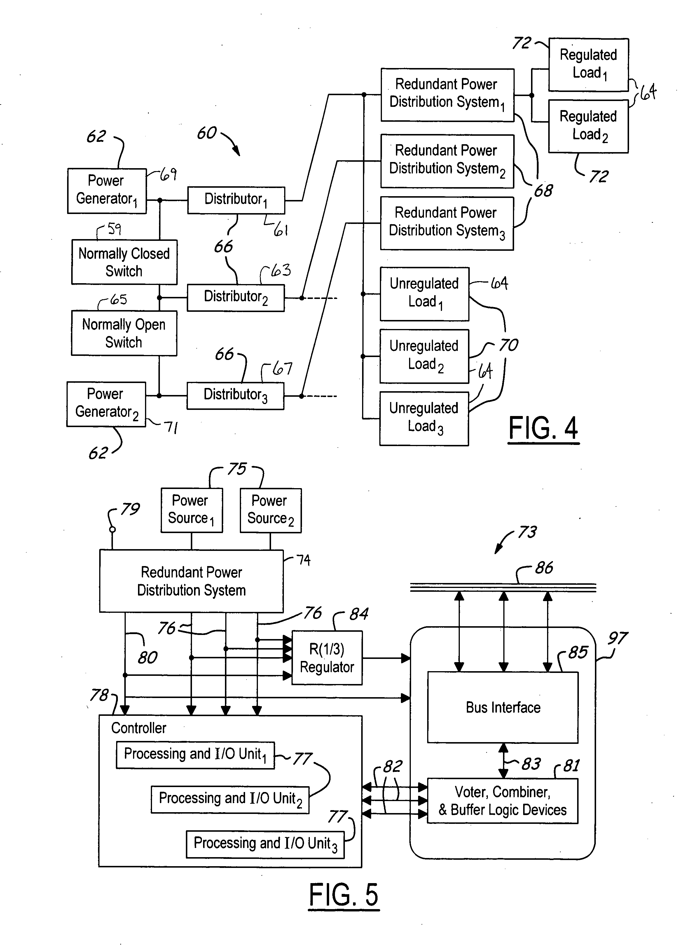
[0042] Also, in the following description an R(M / N) device circuit refers to a redundant circuit having multiple redundant modules or devices with multiple inputs and a common output. Two examples, namely an R(1 / 2) switch and an R(1 / 2) redundant regulator circuit, of an R(M / N) device cir...


PUM


Abstract

A redundant power distribution system (74) that has multiple distribution lines (168) and (174) includes multiple regulators (122). Multiple isolation transformers (124) are coupled to the regulators (122) and have isolation boundaries (261). An R(M / N) device circuit (152) is coupled to the isolation transformers (124). The regulators (122) and the isolation transformers (124) have a non-feedback looped configuration (259) across the isolation boundaries (261).

Description

RELATED APPLICATION [0001] The present invention is related to U.S. Pat. No. 5,654,859, entitled “FAULT TOLERANT POWER DISTRIBUTION SYSTEM”, which is incorporated by reference herein.TECHNICAL FIELD [0002] The present invention relates generally to power distribution systems, and more particularly, to a system and method of redundantly supplying and distributing power from power sources to loads. BACKGROUND OF THE INVENTION [0003] Complex electronic power distribution systems exist and are increasingly relied upon to operate within power plants and within various vehicles, such as aircraft, watercraft, and land-based vehicles. Many electronic components contained in the distribution systems are of a critical nature, whereby, it is preferred that functions performed by these components are continuously available as required. It is therefore desirable that these components do not malfunction or become inoperable. Malfunctioning of any of the components can result in a large-scale syst...

Claims


Application Information

Patent Timeline
IPC IPC(8): H02J1/00
CPCH02J1/00H02J1/102H02J9/06
Inventor SHI, FONG
Owner THE BOEING CO
Learn More