

Bearing surface layer for magnetic motor
- Summary
- Abstract
- Description
- Claims
- Application Information
AI Technical Summary
Benefits of technology
Problems solved by technology
Method used
Image

Examples
first embodiment
I. First Embodiment Magnetic Motor (FIGS. 3 and 4)
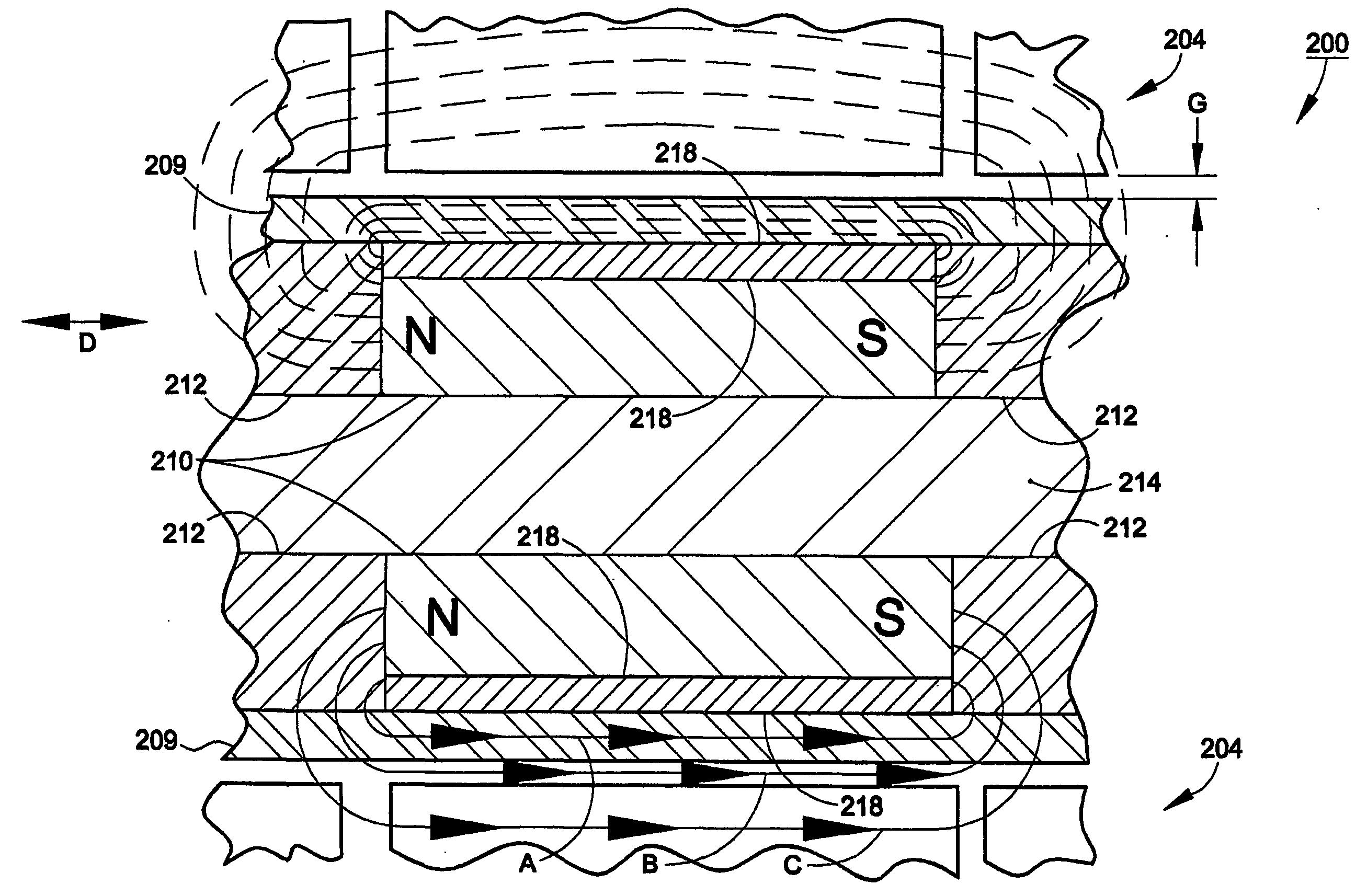
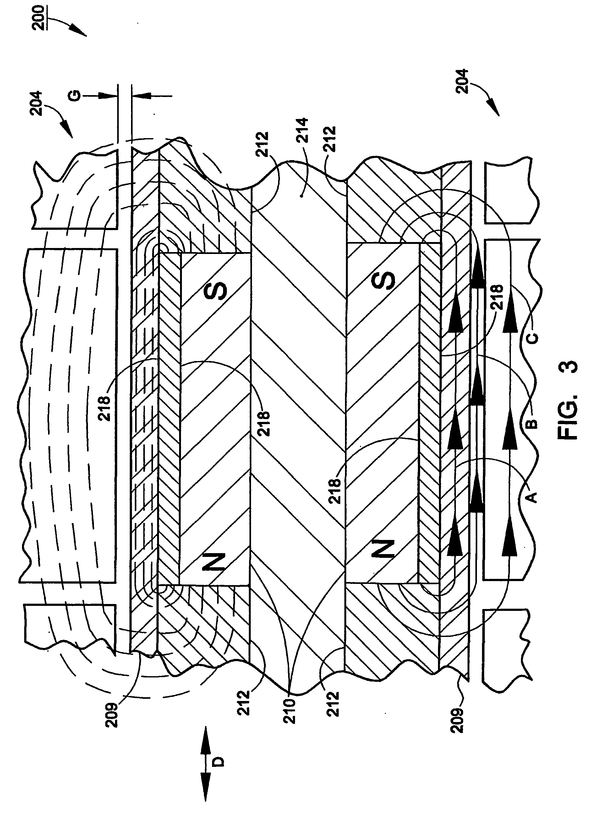
FIGS. 3 and 4 show exemplary magnetic motor 200 according to the present invention. Magnetic motor assembly 200 includes stator 204, sleeve 209, annular permanent magnets 210, pole pieces 212, core 214 and annular spacers 218. Stator 204 is similar to prior art stator 104 and will not be discussed in detail.
Core 214, annular permanent magnets 210, pole pieces 212, annular spacers 218 and shaft sleeve 209 are assembled to form shaft 202, as shown in FIG. 4. Core 214 provides structural support and may be made hollow or solid. Core 214 has a low magnetic permeability (e.g., magnetic permeability of approximately 1.0). In some embodiments of the present invention, the core may be omitted because the stronger and stiffer sleeve materials that can now be used as a shaft sleeve may provide sufficient structural support for the shaft even without a core. If there is no core, the inside of the shaft may be hollow, or, alternatively, the pe...
third embodiment
IV. Third Embodiment of a Magnetic Motor (FIG. 10)
FIG. 10 shows another preferred embodiment of a linear magnetic motor 500. Motor 500 includes stator 504, shaft 502 and bearing 506. Bearing 506 is preferably a bronze bushing.
Shaft 502 includes magnets 510, pole pieces 512, annular spacers 518, shaft sleeve 509 and nut assembly 570. Magnets 510, pole pieces 512, annular spacers 518 and shaft sleeve are similar to their respectively corresponding components in previously-discussed motor 200. In this embodiment, the axial length of two magnets 510 and two pole pieces (“the pole pair pitch”) is preferably 0.922 inches. The nut assembly 570 is structured to accommodate a cap (not shown) by a threaded connection.
Stator 504 includes coils 556, power supply lines 557, pole pieces 558, spacer rings 560, tensioning rod 562 and collar assembly 564. Coils 556 are preferably 115 turn, 19 gauge copper wire. Power supply lines preferably selectively provide 3 phase AC power to the coils to co...
PUM
| Property | Measurement | Unit |
|---|---|---|
| Diameter | aaaaa | aaaaa |
| Magnetic field | aaaaa | aaaaa |
| Hardness | aaaaa | aaaaa |
Abstract
Description
Claims
Application Information