Tunable differential transconductor and adjustment method

a transconductors and differential technology, applied in the field of tunable differential transconductors and tuning methods, can solve the problems of impairing affecting the performance of the transconductors, and only holding the square law model described abov

Inactive Publication Date: 2005-01-13
AGILENT TECH INC
View PDF4 Cites 9 Cited by
  • Summary
  • Abstract
  • Description
  • Claims
  • Application Information

AI Technical Summary

Benefits of technology

The invention provides a tunable differential transconductor that includes a differential pair of FETs connected to a tail current sink. At least one of the FETs is a composite FET having an effective channel dimension that can be changed to tune the differential transconductor. Tunable parameters include offset, transconductance and transconductance linearity. In one embodiment, the tail current is fixed and the transconductance tuning is performed by changing the effective channel dimension. In another embodiment, the transconductance is tuned by tail current tuning and the effective channel dimension is changed to provide a desired transconductance linearity at that conductance. Changing the effective channel dimension to compensate for process and environmental variations avoids the need to trade high current for linearity.

Problems solved by technology

Conventional transconductors have several advantages, including tunable transconductance, low input capacitance, and good linearity for large bias voltages, but have certain limitations.
In high-speed circuits, a small value of L is desirable because a large input capacitance can impair the performance of the transconductor at high speeds.
However, the square law model described above only holds when the MOSFETs have a channel length larger than a process-determined minimum length.
Therefore, in differential tranconductors fabricated using MOSFETs having a channel length approaching the process-defined minimum, tail current tuning becomes a progressively less effective way of tuning the transconductance gm.
The current trend towards lower power supply voltages also reduces the effectiveness of tail current tuning to tune transconductance because a low power supply voltage limits the turn-on voltage (Vgs−VT).
Moreover, a lower power supply voltage also reduces the linearity that can be obtained.

Method used


Image

  • Tunable differential transconductor and adjustment method
  • Tunable differential transconductor and adjustment method
  • Tunable differential transconductor and adjustment method

Examples


Embodiment Construction

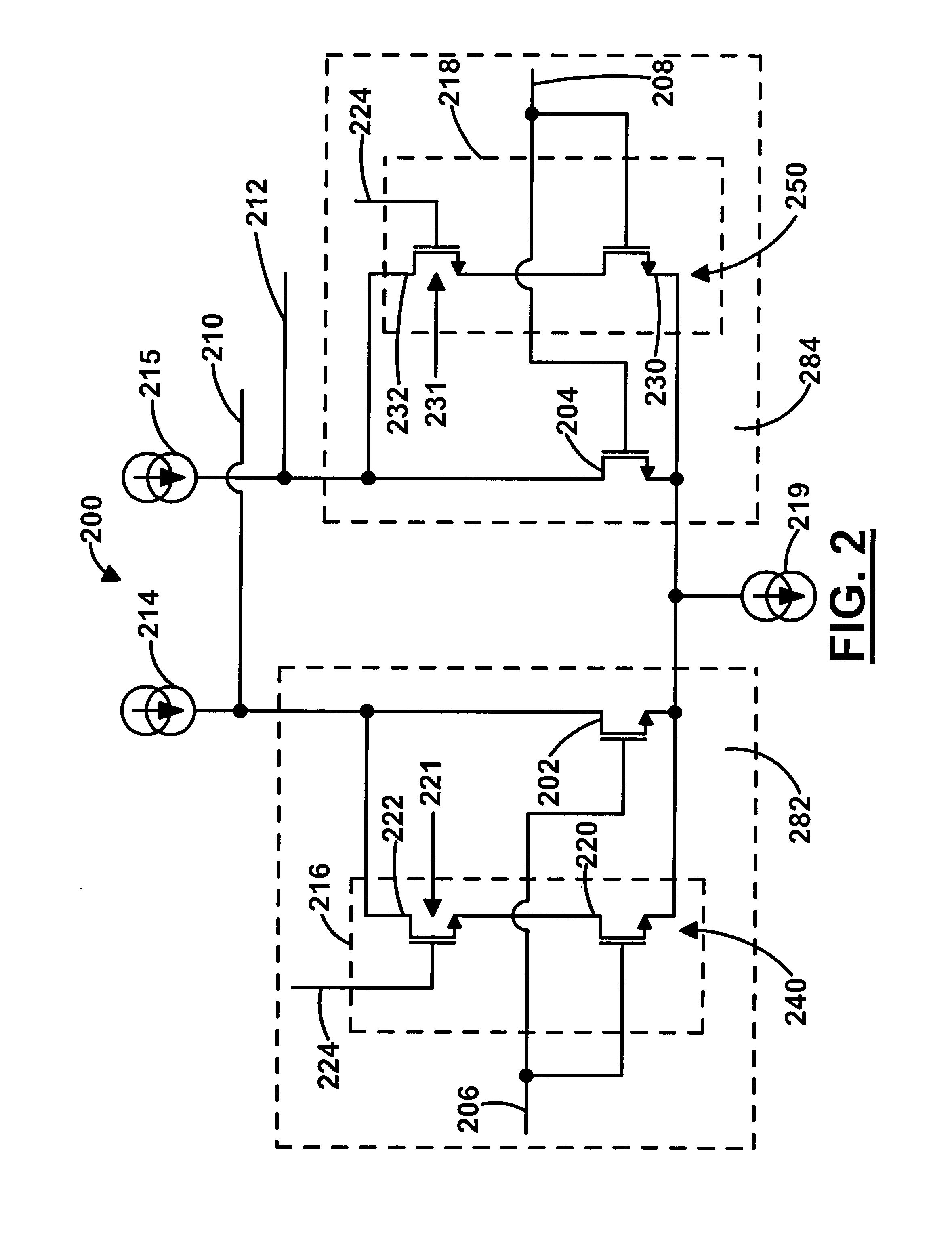
FIG. 2 is a circuit diagram showing a first embodiment 200 of a tunable differential transconductor in accordance with the invention. Differential transconductor 200 is composed of a composite FET 282 and a composite FET 284 connected as a differential pair. Each composite FET is composed of a main FET and a switchable tuning element connected in parallel. The switchable tuning element is operable to change an effective channel dimension of the composite FET.

Composite FET 282 is composed of a main FET 202 and a switchable tuning element 216 connected in parallel. Switchable tuning element 216 is a series circuit 240 composed of an auxiliary FET 220 and a switch 221 connected in series. Series circuit 240 is connected between the source and the drain of main FET 202 and the gate of auxiliary FET 220 is connected to the gate of main FET 202 to connect switchable tuning element 216 in parallel with main FET 202. The nodes where switchable tuning element 216 connects to the drain, gate...


PUM


Abstract

The tunable differential transconductor includes a tail current sink and a differentially-connected pair of FETs connected to the tail current source. At least one of the FETs is a composite FET that includes a main FET connected in parallel with a switchable tuning element. The switchable tuning element is operable to change an effective channel dimension, i.e., at least one of effective channel length and effective channel width, of the composite FET. In the method, a differential transconductor that includes a tail current sink and a differentially-connected pair of composite FETs connected to the tail current sink is provided. The effective channel dimension of at least one of the composite FETs is changed to establish one or more of a desired transconductance, a desired transconductance linearity and a desired offset of the differential transconductor.

Description

TECHNICAL FIELD The technical field of this disclosure is semiconductor circuits, particularly, tunable differential transconductors and methods of tuning the same. BACKGROUND OF THE INVENTION Transconductors are used in circuits to convert voltage signals to current signals. They can be used with capacitors to form integrators or can be used in filter circuits, such as gm−C filters. Conventional transconductors have several advantages, including tunable transconductance, low input capacitance, and good linearity for large bias voltages, but have certain limitations. FIG. 1 is a circuit drawing showing a conventional transconductor constructed using differential pair of MOSFETs. Differential transconductor 100 is composed of a MOSFET 102 and a MOSFET 104 connected as a differential pair. Differential input voltages Vin+ and Vin− are received at an input terminal 106 and an input terminal 108, respectively. Input terminal 106 is connected to the gate of MOSFET 102 and input termina...

Claims


Application Information

Patent Timeline
Patent Type & Authority Applications(United States)
IPC IPC(8): H01L27/088
CPCH01L27/088
Inventor NEFF, ROBERT M. R.
Owner AGILENT TECH INC
Why Eureka
Try Eureka