Low power crystal oscillator

a crystal oscillator, low-power technology, applied in the direction of oscillation generators, generator stabilization, electric devices, etc., can solve the problems of low output signal, high cost, and low output frequency,

Inactive Publication Date: 2005-01-13
RAKON
View PDF6 Cites 53 Cited by
  • Summary
  • Abstract
  • Description
  • Claims
  • Application Information

AI Technical Summary

Benefits of technology

[0009] It is an object of the present invention to provide a crystal oscillator system which provid

Problems solved by technology

This low frequency clock is used to operate the RTC during power-off or standby times. One of the disadvantages of using a tuning fork-type crystal is that the output frequency wanders from the

Method used


Image

  • Low power crystal oscillator
  • Low power crystal oscillator
  • Low power crystal oscillator

Examples


Embodiment Construction

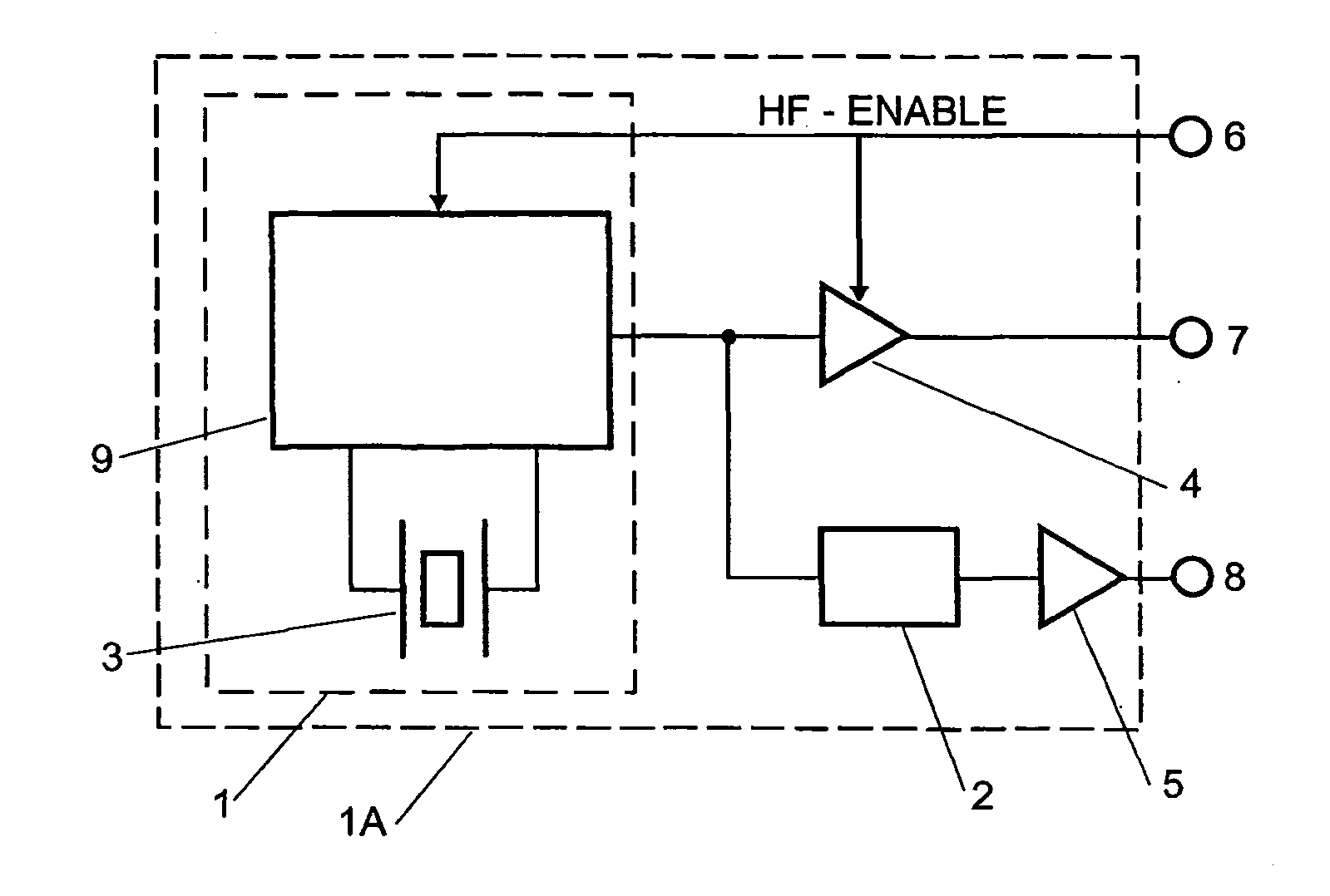
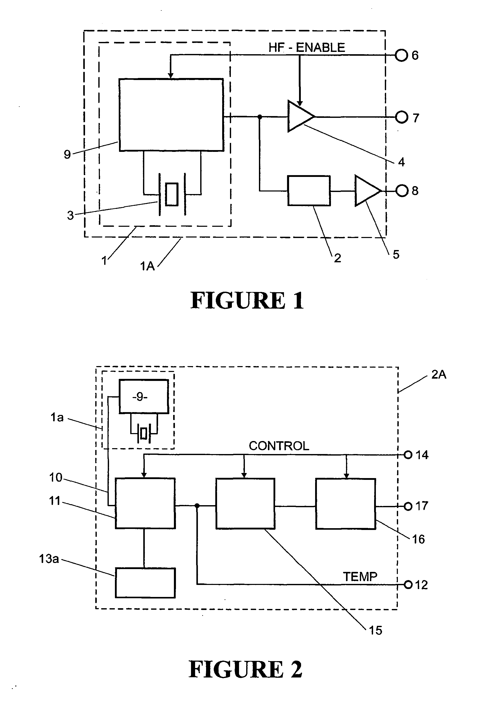
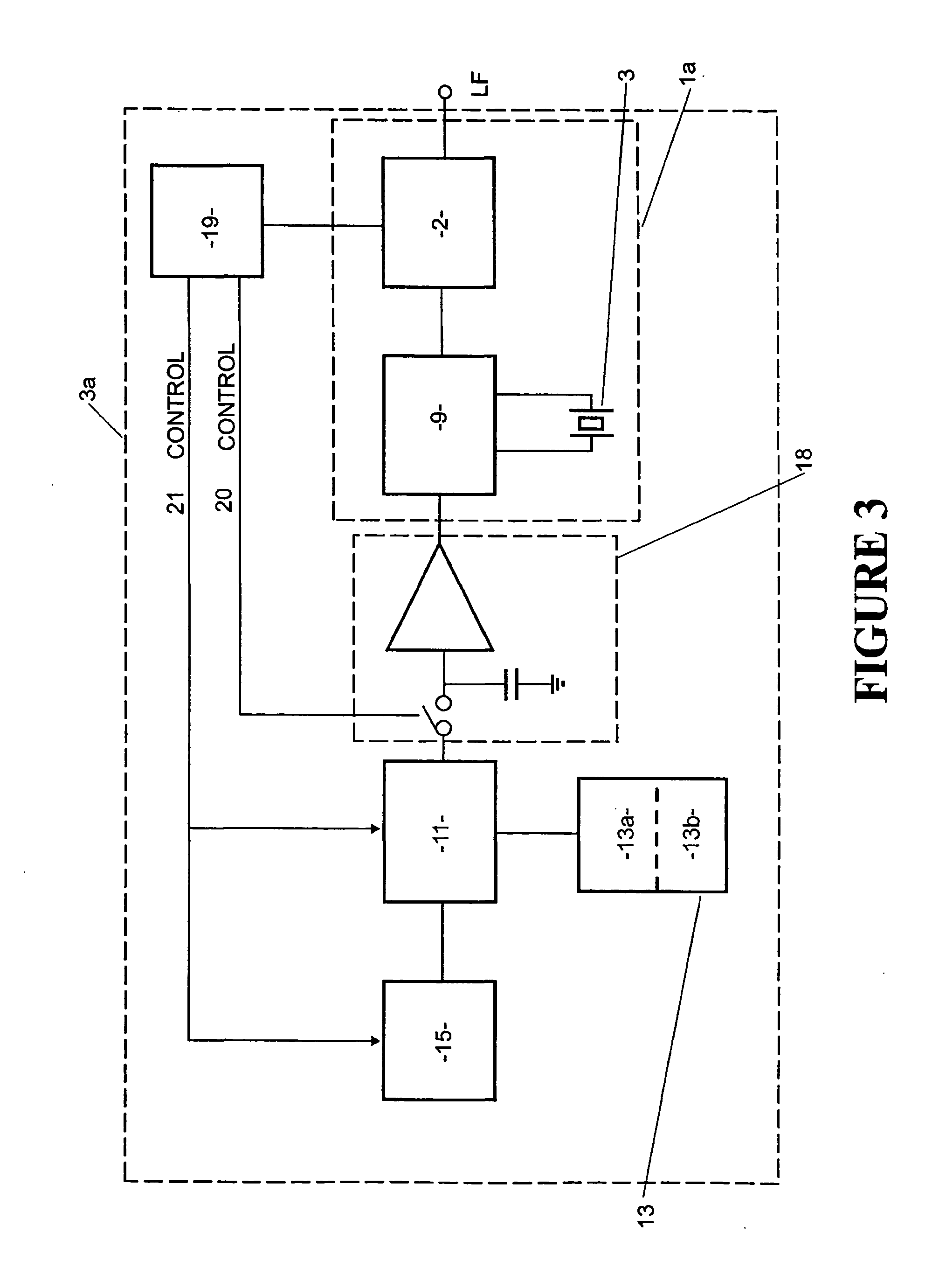
[0041] The present invention relates to a timing system including an integrated circuit having an oscillator that provides both high and low frequency clock signals from a single high frequency crystal without the necessity of a tuning fork crystal. The low frequency signal is available for time-keeping applications, with low power consumption during “idle” periods. The high performance high frequency signal is available on demand for clock and frequency reference use. The oscillator of the present invention provides improved time-keeping accuracy, whilst size, cost and component count is reduced. Furthermore phase noise and other critical parameters of the high frequency oscillator are not compromised. Shock vulnerability, a known problem for tuning fork crystals, is reduced.

[0042] Current technology being discussed herein is microprocessor based, therefore references to “low clock signals” or “low frequency,” mean a real time clock (RTC) signal which is typically 32 kHz. Other fr...


PUM


Abstract

The present invention relates to a timing system including an integrated circuit having an oscillator that provides both high and low frequency clock signals from a single high frequency crystal without the necessity of a tuning fork crystal. The low frequency signal is available for time-keeping applications, with low power consumption during “idle” periods. The high performance high frequency signal is available on demand for clock and frequency reference use. The oscillator of the present invention provides improved time-keeping accuracy, whilst size, cost and component count is reduced. Furthermore, phase noise and other critical parameters of the high frequency oscillator are not compromised. Shock vulnerability, a known problem for tuning fork crystals, is reduced.

Description

CROSS REFERENCE TO RELATED APPLICATIONS [0001] This application claims priority under 37 USC § 119 (a-d) to New Zealand Provisional Application No. 526595 filed Jun. 19, 2003 which is herein incorporated by reference. FIELD OF THE INVENTION [0002] The present invention relates to crystal oscillator systems particularly, but not solely for the provision of low frequency real time clock signals at low standby power in applications which also require a high accuracy clock signal in full operating mode. BACKGROUND OF THE INVENTION [0003] Electronic apparatus frequently requires both a high frequency clock signal, and a low-power, low frequency clock signal. Examples of such equipment are Global Positioning System (GPS) and Code Division Multiple Access (CDMA) radios, and many other applications that use microprocessors. The high frequency signal must be of high spectral and temporal purity and stability. This is commonly derived from AT cut quartz crystals to achieve the required purity...

Claims


Application Information

Patent Timeline
IPC IPC(8): H03B5/36H03B5/32
CPCH03B5/36H03B5/368H03B5/366
Inventor BRIDGER, SIMON
Owner RAKON
Why Eureka
Try Eureka