Electric-powered compressor

a compressor and electric technology, applied in the direction of positive displacement liquid engines, domestic cooling devices, lighting and heating devices, etc., can solve the problems of insufficient reliability and the idea of positively cooling the control circuit for controlling the operation of the semiconductor switching device in the drive circuit, and achieve the effect of improving the reliability of the control circui

Inactive Publication Date: 2005-01-20
DENSO CORP
View PDF11 Cites 23 Cited by
  • Summary
  • Abstract
  • Description
  • Claims
  • Application Information

AI Technical Summary

Benefits of technology

[0007] An object of the present invention is to provide an electric-powered compressor enabling improvement of the reliability of a control circuit in a motor drive circuit even when the motor is not being operated.

Problems solved by technology

In the above art, however, the idea of positively cooling the control circuit for controlling the operation of the semiconductor switching device in the drive circuit has never been seen.
In general, the heat generated by the control circuit itself is less than the semiconductor switching device, but its own heat resistance is low, so there was the problem that when the motor was not being operated, the reliability could not be sufficiently secured depending on the temperature environment in which the electric-powered compressor was arranged.

Method used


Image

  • Electric-powered compressor
  • Electric-powered compressor
  • Electric-powered compressor

Examples


first embodiment

[0020] First Embodiment

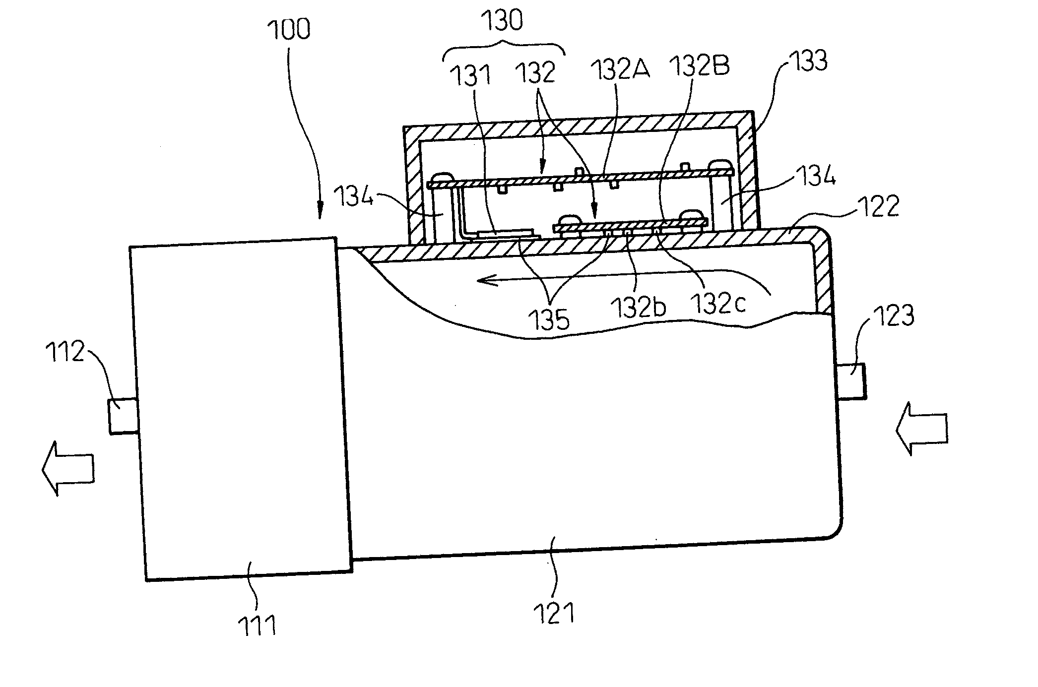
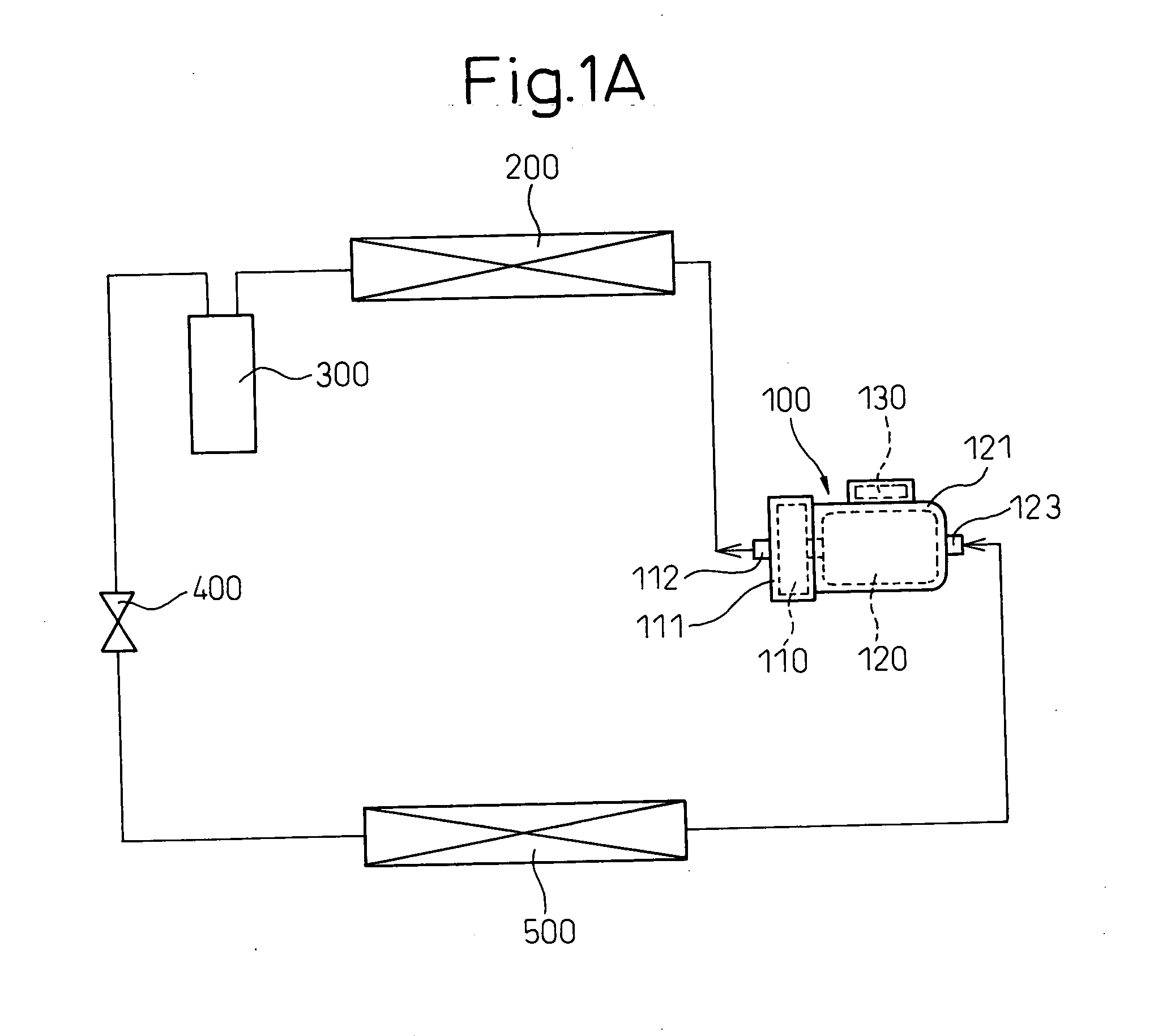
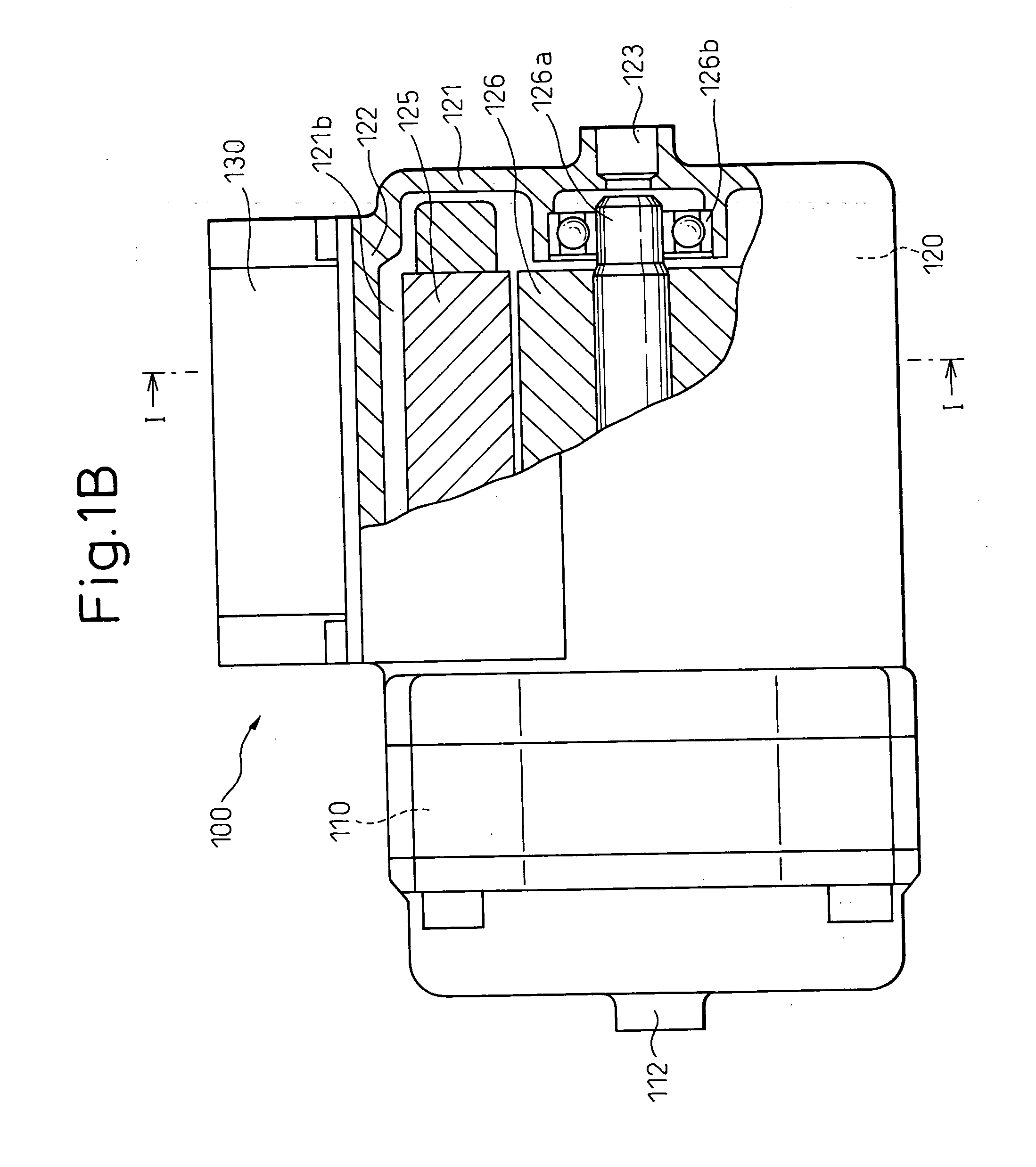
[0021] Below, a first embodiment of the present invention will be explained based on FIGS. 1A and 1B to FIG. 4. FIG. 1A is a schematic view of a vehicular steam compression type refrigeration cycle using an electric-powered compressor 100 with an integral motor drive circuit according to the present embodiment, FIG. 1B is a partial cross-sectional view of an electric-powered compressor, and FIG. 1C is a cross-sectional view along the line I-I of FIG. 1B. FIG. 2 is a schematic view of a position of mounting an electric-powered compressor 100 in an engine compartment 1a of the vehicle 1. FIG. 3 is a partial cross-sectional view of an electric-powered compressor 100 in the present embodiment. FIG. 4 is a circuit diagram of the configuration of an inverter circuit 130.

[0022] As shown in FIG. 1A, 200 is a condenser for cooling the refrigerant discharged from the electric-powered compressor 100, while 300 is a receiver (vapor-liquid separator) for separating the re...

second embodiment

[0043] Second Embodiment

[0044] A second embodiment of the present invention is shown in FIG. 5. FIG. 5 is a partial cross-sectional view showing the electric-powered compressor 100 in the second embodiment.

[0045] Here, the electronic circuit devices 150 of the control circuit 132 are provided on a single printed circuit board 132A and the printed circuit board 132A is affixed to a support member 134. Further, the electronic circuit devices 150 of the circuit particularly inferior in heat resistance in the control circuit 132 (the photo coupler 132b etc. as in the first embodiment) are made to abut against the front end of the heat conduction path 124 sticking out integrally from the side wall 122.

[0046] In this way, even when the control circuit 132 is integrally provided and is fixed to the support member 134, it is possible to dissipate the heat from the electronic circuit devices 150 to the side wall 122 by the heat conduction path 124, so it is possible to obtain similar effec...


PUM


Abstract

An electric-powered compressor comprised of a compression mechanism 110 for sucking in and compressing a refrigerant and an electric motor 120 for driving the compression mechanism formed integrally and provided at a refrigerant suction side of the compression mechanism with a motor drive circuit 130 for driving the motor, wherein at least part of a control circuit 132 provided at the motor drive circuit and controlling the operation of a switching device 131 for adjusting the power supplied to the motor is provided abutting against the surface of the refrigerant suction side 121 or a heat conduction path 124 extending from the surface.

Description

BACKGROUND OF THE INVENTION [0001] 1. Field of the Invention [0002] The present invention relates to an electric-powered compressor having a compression mechanism for sucking in and compressing a refrigerant, an electric motor for driving the compression mechanism, and an inverter circuit or other motor drive circuit for driving the motor and is effective if applied to a vehicular steam compression type refrigeration cycle. [0003] 2. Description of the Related Art [0004] As an electric-powered compressor of the related art, for example, as described in Japanese Unexamined Patent Publication No. 2000-291557, there is known one comprised of a compression mechanism and a motor formed integrally and having a drive circuit for driving the motor attached to the refrigerant gas suction side of the compression mechanism. More specifically, the housing in which the motor is housed is provided with a refrigerant suction port and the inverter in the drive circuit is attached in close contact w...

Claims


Application Information

Patent Timeline
Patent Type & Authority Applications(United States)
IPC IPC(8): B60H1/00F04B39/00F04B39/06F04C23/00F04C29/00F04C29/04F25B1/04H02K9/22H02K11/00
CPCB60H2001/00614F04C23/008F04C29/0085F25B2600/021F04C2240/808F25B1/04F04C29/047
Inventor SHINDO, YUSUKEIRIYAMA, KENJI
Owner DENSO CORP
Why Eureka
Try Eureka